A Method of Focus Positioning of X-ray Machine Based on Adjusting Long Hole

An X-ray machine and long-hole technology, applied in the field of X-ray machines, can solve the problems of continuous adjustment of the fixed state, increased workload of welding and removal of temporary hooks, and heavy workload, so as to improve the efficiency of adjustment and positioning, and the adjustment and positioning are convenient and fast. The effect of low investment in production and use

Active Publication Date: 2017-06-16
MCC TIANGONG GROUP
View PDF7 Cites 0 Cited by
  • Summary
  • Abstract
  • Description
  • Claims
  • Application Information

AI Technical Summary

Problems solved by technology

The way of fixing the temporary hook on the top not only causes damage to the base material, but also increases the workload of welding and removing the temporary hook. At the same time, when it is adjusted and fixed, it requires personnel to climb to the top of the cylinder or two people to carry the ray machine inside the cylinder The danger is increased with factors such as the rotation of the tire; although it is more convenient to fix and adjust the adjustment machine in the transillumination room, it can only perform a single transillumination with the source outside. In addition, the device is heavy and moves slowly, which makes the transillumination efficiency lower; setting up temporary support and fixing requires a large number of supporting members and auxiliary personnel to set up the support, the workload is large and generally cannot fully meet the requirements of accuracy and efficiency; and although the temporary support sticks used in the past are tied with iron wires, it is convenient to enter and exit the closed container. The above problems can also be solved without being restricted by other factors, but the adjustment efficiency is still low, the stability is poor, the adjustment accuracy is not high, and continuous adjustment in a fixed state cannot be performed.

Method used


Image

  • A Method of Focus Positioning of X-ray Machine Based on Adjusting Long Hole
  • A Method of Focus Positioning of X-ray Machine Based on Adjusting Long Hole
  • A Method of Focus Positioning of X-ray Machine Based on Adjusting Long Hole

Examples


Embodiment Construction

[0021] The present invention will be further described in detail below through the specific examples, the following examples are only descriptive, not restrictive, and cannot limit the protection scope of the present invention with this.

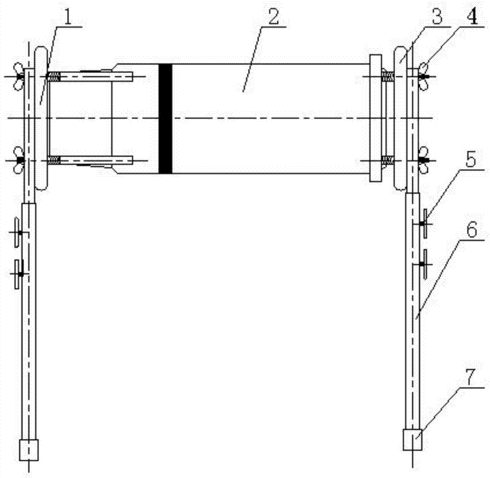
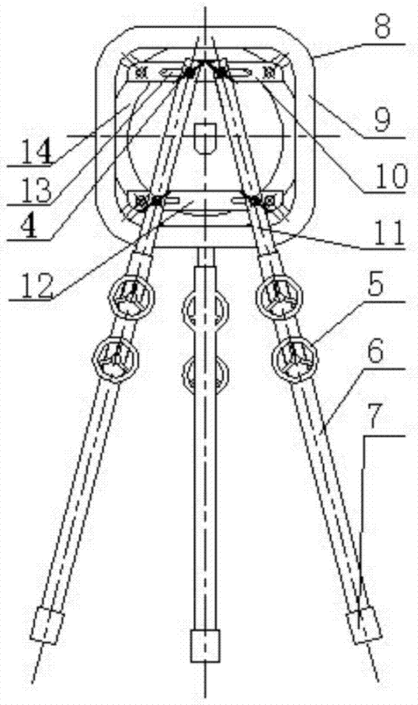
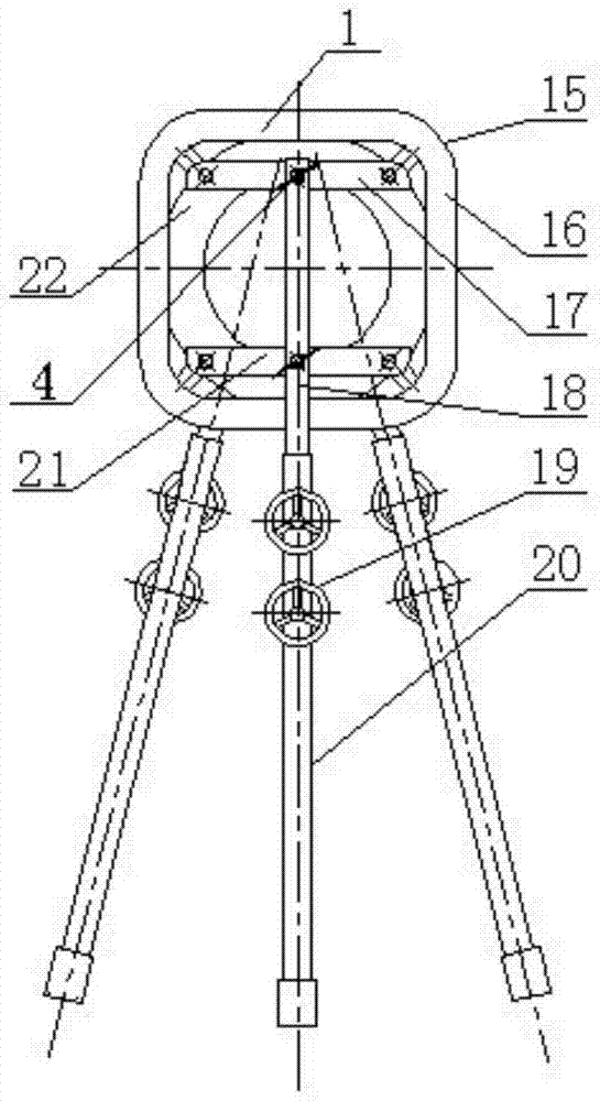
[0022] A method for positioning the focus of an X-ray machine based on adjusting a long hole. The adjustable bracket includes a double-leg adjustable bracket and a single-leg adjustable bracket. The steps of the method are:

[0023] (1) Install the double-leg adjustable bracket 3 on the front end of the X-ray machine 2: the double-leg adjustable bracket includes the front outer square ring 9, the front inner circular ring 14, the front upper fixing plate 10, the front lower fixing plate 12, the front end Inner telescoping rod 11, front-end outer sleeve 6 and front-end locking handwheel 5 cut and fix the front-end inner circular ring in the front-end outer square ring, and the four corners of the front-end outer square ring are shaped with rou...


PUM


Abstract

The invention relates to a method for positioning the focus of an X-ray machine based on adjusting a long hole, comprising the following steps: installing a double-leg adjustable bracket at the front end of the X-ray machine; installing a single-leg adjustable bracket at the rear end of the X-ray machine; Preliminary adjustment of the height of the X-ray machine and its separation angle; position and place it according to the beam direction and focal length required by the process, and at the same time visually observe the focal length to meet the requirements; measure and adjust the positioning and adjustment of the double leg adjustable bracket and the single leg by the central exposure method and eccentric exposure method The legs can adjust the bracket until the positioning accuracy meets the requirements of the detection process to complete the focus positioning. The invention is easy to operate, scientific and reasonable, has low cost, shortens the adjustment time of the ray machine, facilitates focus positioning, and improves work efficiency.

Description

[0001] This application is a divisional application with the patent application number 201310084211.3, the patent name is a method for positioning the focus of an X-ray machine by using an adjustable bracket, and the filing date is 2013.03.15. technical field [0002] The invention belongs to the field of X-ray machines, in particular to a method for positioning the focus of an X-ray machine based on adjusting long holes. Background technique [0003] At present, when the X-ray machine detects the ring and longitudinal welds of the cylindrical container, due to the requirements of the focal length and angle of the transmitted radiation, it is necessary to fix and accurately adjust the position of the X-ray machine and locate the focus. In terms of the fixation and adjustment of the previous X-ray machine, the newly-manufactured cylindrical container is generally carried out by means of rope hanging by welding temporary hooks, adjustment and fixation of the adjustment machine,...

Claims


Application Information

Patent Timeline
Patent Type & Authority Patents(China)
IPC IPC(8): G01N23/04H05G1/02
Inventor 李显峰贾立刚王繁荣张育红
Owner MCC TIANGONG GROUP
Why Eureka
Try Eureka