Check patentability & draft patents in minutes with Patsnap Eureka AI!

Airborne laser communication boundary layer effect optical compensation method

An airborne laser and optical compensation technology, applied in optics, optical components, instruments, etc., can solve problems such as limited correction range of deformable mirrors, failure to work, and reduced optical quality of space laser communication terminals, so as to improve environmental adaptability and increase The effect of flexibility

Inactive Publication Date: 2015-06-24
CHANGCHUN UNIV OF SCI & TECH
View PDF4 Cites 5 Cited by
  • Summary
  • Abstract
  • Description
  • Claims
  • Application Information

AI Technical Summary

Problems solved by technology

Both will greatly reduce the optical quality of the space laser communication terminal, seriously affect the performance of the system, or even fail to work, so measures must be taken to alleviate the impact
In the existing patents and literatures, the method of adaptive optics Hartmann sensor and deformable mirror is used to correct the effect of atmospheric turbulence, but the correction range of the deformable mirror is limited, and it is difficult to complete all the effects of the boundary layer alone, especially the inclusion layer. Correction method of flow laminar effect

Method used


Image

  • Airborne laser communication boundary layer effect optical compensation method

Examples


Embodiment Construction

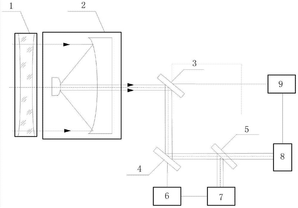
[0016] Optical compensation methods for boundary layer effects in airborne laser communications, such as figure 1 As shown, after the light beam passes through the defocus compensation mirror 1, it is narrowed by the space laser communication optical antenna 2, and then reflected by the optical vibrating mirror 3 and incident on the deformable mirror 4, and then reflected by the deformable mirror 4 to the beam splitter 5, and then passed through Light splitting, one beam to the wavefront detector 7, one beam to the spot position and size detector 8; the wavefront correction controller 6 is connected to the deformable mirror 4 and the wavefront detector 7 respectively through circuits to form a closed-loop control; The mirror controller 9 is respectively connected with the optical vibrating mirror 3 and the light spot position and size detector 8 through a circuit to form a closed-loop control.

[0017] The positions of the optical vibrating mirror 3 and the deformable mirror 4...


PUM


Abstract

The invention discloses an airborne laser communication boundary layer effect optical compensation method and belongs to the technical field of space laser communication. An out-of-focus compensation lens, a space laser communication optical antenna, an optical vibration lens, a deforming lens, a beam splitter, a wavefront correcting controller, a wavefront detector, a light spot position and size detector and a vibration lens controller. The out-of-focus compensation lens is arranged in front of the space laser communication optical antenna and is arranged perpendicular to a horizontal plane. The wavefront correcting controller is connected with the deforming lens and the wavefront detector through circuits respectively. The vibration lens controller is connected with the optical vibration lens and the light spot position and size detector through circuits respectively. According to the method, light beam wavefront distortion, arrival angle fluctuating, light beam deflection and additional focal length effect caused by the pneumatic optical boundary layer effect can be relieved, and the environmental suitability of a space laser communication terminal on an airborne platform is improved.

Description

technical field [0001] The invention belongs to the technical field of space laser communication, and in particular relates to an optical compensation method for boundary layer effect of airborne laser communication. Background technique [0002] For the laser communication terminal of the airborne platform, the high-speed flight of the aircraft in the atmospheric channel will cause the aero-optical boundary layer effect. The boundary layer effect is very complex, and the simplified analysis can be regarded as laminar layer effect and turbulent layer effect. The main manifestations are: the laminar layer effect is equivalent to a negative lens, which causes the defocusing of the laser communication optical system and the beam deflection; the turbulent layer effect causes the beam wavefront distortion and the angle of arrival fluctuation. Both will greatly reduce the optical quality of the space laser communication terminal, seriously affect the performance of the system, or...

Claims


Application Information

Patent Timeline
Patent Type & Authority Applications(China)
IPC IPC(8): G02B26/06
Inventor 胡源高天元姜会林佟首峰张立中
Owner CHANGCHUN UNIV OF SCI & TECH
Features
  • R&D
  • Intellectual Property
  • Life Sciences
  • Materials
  • Tech Scout
  • Unparalleled Data Quality
  • Higher Quality Content
  • 60% Fewer Hallucinations
Learn More