
Intelligent image positioning intermissive pumping controller

An image positioning and controller technology, which is applied in the program control and electrical program control of the sequence/logic controller, can solve problems such as well jamming and loading, human or animal hazards, and burning motors, so as to ensure production safety High degree of automation, high degree of automation, and simple operation

Inactive Publication Date: 2015-06-24
洪继波
View PDF10 Cites 3 Cited by
  • Summary
  • Abstract
  • Description
  • Claims
  • Application Information

AI Technical Summary

Problems solved by technology

However, these methods cannot guarantee that the pumping unit will stop at the upper and lower dead points when the pumping unit stops. If the well stop time is too long, the oil in the oil pump and the oil pipe will solidify, causing the oil pump to fail to go back when the well is started, or the well will get stuck or The load of well start-up is heavy, which leads to serious consequences such as power consumption and motor burning. Nowadays, most oil wells are manually braked. If manual operation cannot ensure the standard operation when stopping the well, after the stop, the counterweight of the pumping unit will swing back and forth to cause damage to the oil well. Serious damage, such as impact on the motor, distribution box and power grid, etc.; if there is no safety net around the oil well, it may cause harm to people or animals on the site when the automatic well is pumped between the pumping units

Method used


Image

  • Intelligent image positioning intermissive pumping controller
  • Intelligent image positioning intermissive pumping controller
  • Intelligent image positioning intermissive pumping controller

Examples


Embodiment Construction

[0019] The following is a further description of the intelligent image positioning and inter-drawing controller of the present invention in conjunction with the accompanying drawings:

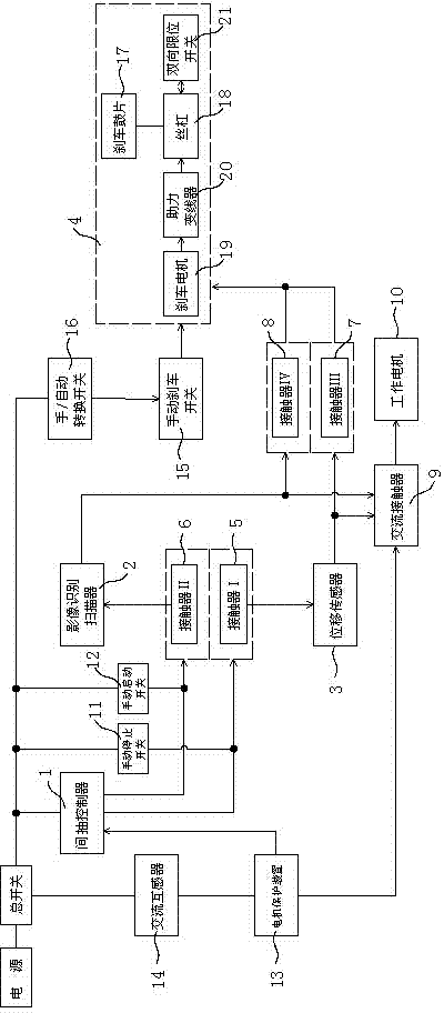
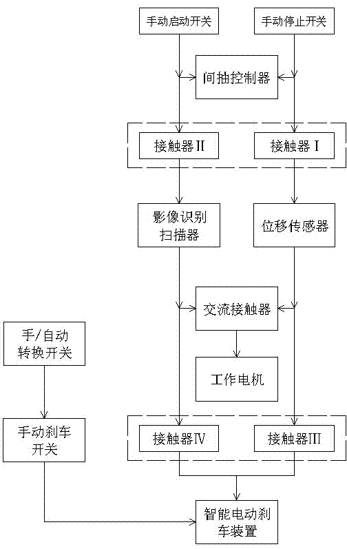
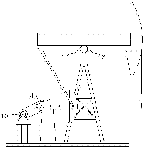
[0020] The intelligent image positioning inter-pumping controller of the present invention is composed of an image recognition scanner 2, a displacement sensor 3 and an intelligent electric brake device 4 on the basis of the inter-pumping controller 1 originally installed on the pumping unit.

[0021] The entire intelligent image positioning inter-pumping controller is connected to the AC power supply, and the circuit connection relationship is as follows: inter-pumping controller 1, contactor Ⅰ5, displacement sensor 3, contactor Ⅲ7 and intelligent electric brake device 4 are sequentially connected in circuit; inter-pumping controller 1 , contactor II6, image recognition scanner 2, contactor IV8 and intelligent electric brake device 4 are circuit-connected in sequence; displacement sensor 3 and ...


PUM


Abstract

The invention relates to the field of auxiliary equipment of oil pumping units, in particular to an intelligent image positioning intermissive pumping controller. The intelligent image positioning intermissive pumping controller is composed of an intermissive pumping controller, a brake device, an image recognizer and a positioning sensor, wherein the intermissive pumping controller, the brake device and the image recognizer are installed on an oil pumping unit, the positioning sensor is arranged at a support point of a walking beam of the oil pumping unit, a power source, a total switch, the intermissive pumping controller, a contactor I, the positioning sensor, a contactor III and the brake device are sequentially connected in a circuit, the intermissive pumping controller, a contactor II, the image recognizer, a contactor IV and the brake device are sequentially connected in a circuit, the positioning sensor and the image recognizer are both connected to a work motor through an alternating current contactor, the contactor I and the contactor II are interlocked, and the contactor III and the contactor IV are interlocked. The image recognizer and the positioning sensor are added based on an original intermissive pumping controller, the on-site conditions can be recognized through the image recognizer when a well is started and stopped, and the positioning sensor can detect whether the movement state of the oil pumping unit reaches an upper / lower dead center and enables the oil pumping unit to be accurately stopped at the upper / lower dead center.

Description

technical field [0001] The invention relates to the field of auxiliary equipment for pumping units, in particular to an intelligent image positioning inter-pumping controller. Background technique [0002] Now the oil production of oil wells is gradually decreasing. In order to save energy, oil wells need to be intermittently pumped, and the intermittent pumping methods are mostly controlled by timing, detection of motor current, and liquid level in oil pipes to control the start and stop of pumping units. However, these methods cannot guarantee that the pumping unit will stop at the upper and lower dead points when the pumping unit stops. If the well stop time is too long, the oil in the oil pump and the oil pipe will solidify, causing the oil pump to fail to go back when the well is started, or the well will get stuck or The load of well start-up is heavy, which leads to serious consequences such as power consumption and motor burning. Nowadays, most oil wells are manually...

Claims


Application Information

Patent Timeline
Patent Type & Authority Applications(China)
IPC IPC(8): G05B19/04
CPCG05B19/04
Inventor 洪继波洪泽远
Owner 洪继波
Learn More