Power transmission apparatus, power reception apparatus, and wireless power transfer system

A power receiving device and wireless power technology, applied in circuit devices, electromagnetic wave systems, electromagnetic measurement devices, etc., can solve the problems of heating metal foreign objects and reducing power transmission efficiency.

Active Publication Date: 2015-06-24
PANASONIC INTELLECTUAL PROPERTY MANAGEMENT CO LTD
View PDF6 Cites 23 Cited by
  • Summary
  • Abstract
  • Description
  • Claims
  • Application Information

AI Technical Summary

Problems solved by technology

[0004] In the above-mentioned wireless power transmission system, if the position of the power transmitting and receiving coil is shifted during power transmission, not on

Method used


Image

  • Power transmission apparatus, power reception apparatus, and wireless power transfer system
  • Power transmission apparatus, power reception apparatus, and wireless power transfer system
  • Power transmission apparatus, power reception apparatus, and wireless power transfer system

Examples


Embodiment approach 1

[0089] Figure 5 It is a block diagram showing a schematic configuration of the wireless power transmission system according to the first embodiment of the present invention. This wireless power transmission system includes a power transmitting device 100 and a power receiving device 200 , and can wirelessly transmit electric power from the power transmitting device 100 to the power receiving device 200 . The power transmitting device 100 is, for example, a wireless charger, and the power receiving device 200 may be, for example, a device equipped with a secondary battery such as a portable information terminal or an electric vehicle. In this embodiment, the aforementioned position detection device is provided on the side of the power transmission device 100 . Therefore, the power transmitting device 100 can not only transmit electric power to the power receiving device 200 but also detect whether or not the position of the power receiving resonator 210 in the power receiving...

Embodiment approach 2

[0145] Figure 8 It is a block diagram showing a schematic configuration of a wireless power transmission system according to a second embodiment of the present invention.

[0146] The basic configuration of this embodiment is the same as that of Embodiment 1, but differs in that the power transmission coil included in the power transmission resonator 110 and the detection coil for positioning are different coils. By providing an additional detection coil for position alignment, not only does a switch between the power transmission resonator 110 and the oscillation circuit 150 become unnecessary, but also the detection coil and the power transmission coil can be arranged at different positions, so that the degree of freedom in the design of the power transmission device 100 is improved. Also improve.

[0147]In addition, in an environment where the power receiving coil moves during power transmission (for example, an on-board charger or a self-propelled robot supplies power d...

Embodiment approach 3

[0150] Figure 9 It is a block diagram showing a schematic configuration of a wireless power transmission system according to a third embodiment of the present invention.

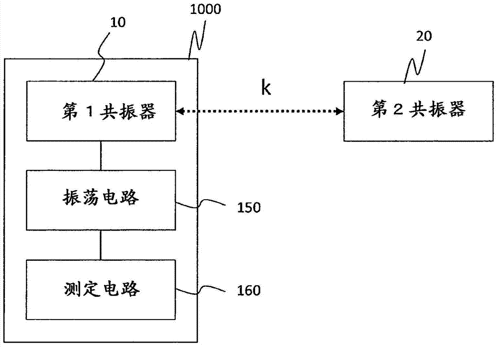
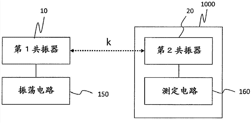
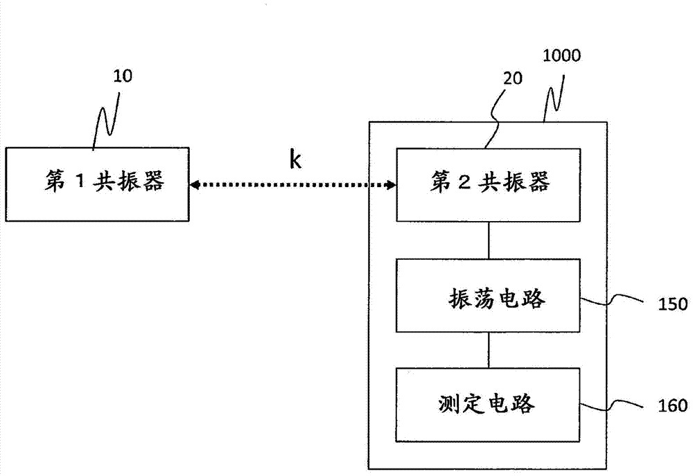
[0151] The basic structure of this embodiment is the same as Embodiment 1, but in the figure 1 changed the idea of image 3 The concept differs in that the power receiving device 200 mounts the oscillation circuit 250 and the measurement circuit 260 for alignment, and that the power transmission resonator 110 includes a parallel capacitor and resonates at a resonance frequency fr.

[0152] In some cases, the power receiving device 200 is larger than the power transmitting device 100 . For example, a large power receiving device 200 such as a tablet terminal may be charged from a small power transmitting device 100 . In such a case, if the power transmitting device 100 has the prompting element 170 for alignment, the prompting element 170 will be covered by the power receiving device 200 , and there is a ...


PUM


Abstract

A power transmission apparatus oscillates alternating current power at a first frequency (f1) which is lower than a resonant frequency (fr) of the second resonator and at a second frequency (f2) which is higher than the resonant frequency (fr). The power transmission apparatus measures an inductance value Lin (f1) and an inductance value Lin (f2). The inductance value Lin (f1) is measured when the oscillation circuit oscillates alternating current power at the first frequency (f1), and the inductance value Lin (f2) is measured when the oscillation circuit oscillates alternating current power at the second frequency (f2). The power transmission apparatus calculates a coupling coefficient k by using an expression represented by k 2 = 1-Lin(f2)/Lin(f1), to detect relative position of the second resonator to the first resonator on the basis of the coupling coefficient k.

Description

technical field [0001] The present invention relates to a position detection device for detecting relative positions between resonators. In addition, the present invention also relates to a power transmission device, a power reception device, and a wireless power transmission system that include such a position detection device and are used for wireless power transmission that transmits electric power in a non-contact manner. Background technique [0002] In recent years, various wireless power transmission systems have been developed for wireless charging in mobile electronic devices such as mobile phones and electric vehicles, and EV devices. In the wireless power transmission technology, there are an electromagnetic induction method and a magnetic field resonance method in which a plurality of coils face each other, and an electric field coupling method in which a plurality of metal plates face each other. The electromagnetic induction wireless power transmission system ...

Claims


Application Information

Patent Timeline
IPC IPC(8): H02J17/00
CPCH02J50/90H02J50/12H02J7/00304G01B7/003G01B2210/58G01R27/2611
Inventor 浅沼健一山本浩司
Owner PANASONIC INTELLECTUAL PROPERTY MANAGEMENT CO LTD
Why Eureka
Try Eureka