
Method and tool for forming tunnel type hole

A tunnel-type, tool-based technology, which is applied in manufacturing tools, welding equipment, metal processing, etc., can solve the problems of large heat dissipation area, difficult to clean, and low efficiency, and achieve the effect of overcoming low efficiency and increasing production costs

Inactive Publication Date: 2015-07-01
BEIJING FSW TECH
View PDF5 Cites 3 Cited by
  • Summary
  • Abstract
  • Description
  • Claims
  • Application Information

AI Technical Summary

Problems solved by technology

When the brazing process is selected, there may be local solder loss, unwelded water leakage, and the lost solder will block the channel
When other welding methods are used, although the disadvantages of brazing can be avoided, the whole process requires multiple processes such as milling grooves, processing cover plates, capping, welding, etc., and the efficiency is not high
Second, the internal holes of metal castings can also be formed by sand cores, but if the oil passage is slender and complicated, the sand cores are easy to break, making it difficult to manufacture, and it is difficult to clean up after casting
The cost of this method is low. Although it can basically meet the heat dissipation requirements, the flow rate of the water channel will be limited by the cross-sectional area of ​​the copper tube. The gap between the copper tube and the substrate needs to be filled, which cannot form a large heat dissipation area and cannot meet certain rapid heat dissipation requirements. Structural Requirements
The above three aspects are the technical problems faced by the current manufacturing process of metal cooling plates. The efficiency of preparing metal cooling plates by traditional processes is low, and to a certain extent increases the production cost of structural parts. It is the key to eliminate these unfavorable factors through technological innovation. Important topics in the field of study

Method used


Image

  • Method and tool for forming tunnel type hole

Examples


Embodiment Construction

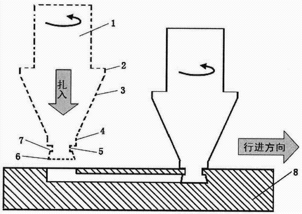
[0014] refer to figure 1 , a tool for preparing a tunnel-shaped hole on a workpiece, the tool is composed of a middle section, a shank 1 and a friction head. One end of the middle section is integrally connected with the handle 1, and the other end of the middle section is integrally connected with the friction head. The middle section is made up of a first cylindrical section 2, a conical section 3 and a second cylindrical section 4, one end of the first cylindrical section 2 is connected with the handle 1 as a whole, and the other end of the first cylindrical section 2 is connected with the conical section 3. One end is connected as a whole, and the other end of the conical section 3 is connected with one end of the friction head as a whole. The rubbing head is composed of a neck 5 and a head 6, the outer diameter of the neck 5 is smaller than that of the head 6, and the cross section of the rubbing head is inverted T-shaped. After the middle section is integrated with the...


PUM

PropertyMeasurementUnit
Thicknessaaaaaaaaaa

Abstract

The invention discloses a method and a tool for forming a tunnel type hole. The tool is composed of a middle section, a handle portion and a friction head; one end of the middle section is integrally connected with the handle portion, while the other end of the middle section is integrally connected with the friction head; the section of the friction head is inverted T-shaped, and the friction head is composed of a neck portion and a head portion; the outer diameter of the neck portion is smaller than the outer diameter of the head portion; the middle section is integrally connected with the friction head; an annular groove is formed between the axial end faces of the friction head and the middle section. The tool has the advantages of high preparation efficiency and low cost.

Description

technical field [0001] The invention relates to a method and a tool for preparing tunnel-shaped holes, which are suitable for preparing tunnel-shaped holes in metal materials and some plastic non-metallic materials. Background technique [0002] The metal block structure with regular tunnel-type holes inside has very important application value in specific industrial fields. Such as cooling plate with water-cooling circulation tank inside, circulation device with oil circuit, etc., this type of structure is widely used in electronics, aviation, aerospace and other fields, and is used for forced rapid cooling of high-heating parts. At present, there are mainly the following methods for preparing tunnel holes in metal block materials: the first method is to use a milling machine to process grooves, and then cover them with metal plates and weld them to form channels. The welding process can be brazing or electron beam welding. , laser welding, friction stir welding and other ...

Claims


Application Information

Patent Timeline
IPC IPC(8): B23K20/12B26F1/26
CPCB23K20/1215B26F1/26
Inventor 孟强栾国红董春林张坤
Owner BEIJING FSW TECH
Learn More