High-temperature-sheet-combination convex vacuum glass provided with edges sealed by sealing grooves and provided with mounting hole(s)

A technology of vacuum glass and sealing groove, applied in glass production, glass forming, glass re-molding and other directions, can solve the problems of inability to produce tempered vacuum glass, lack of support for upper and lower glass, and lack of vacuum glass, etc. Achieve the effect of increased heating rate, uniform and reliable sealing, and elimination of variable deformation

Inactive Publication Date: 2015-07-01
戴长虹
View PDF6 Cites 2 Cited by
  • Summary
  • Abstract
  • Description
  • Claims
  • Application Information

AI Technical Summary

Problems solved by technology

[0002] As a new type of glass with the most energy-saving potential, vacuum glass has achieved large-scale production after more than ten years of research and development, and has been well applied in many fields, especially in the construction field; but there are also obvious The shortcomings are mainly low production efficiency, small production capacity, and inability to produce tempered vacuum glass, etc., which limit its popularization and application in a wider range; the existing large-scale production of vacuum glass uses high temperature (430-480°C) normal pressure The production process of lower edge sealing, low temperature (180-300°C) vacuuming and sealing, because it needs to be kept warm for a period of time at the edge sealing temperature, generally 15-20min, so that the solder can fully melt and flow and bond to obtain a higher sealing Therefore, tempered glass will be annealed during the edge sealing process under high temperature and long-term action. Although the initial stress of tempered glass can be made very high, only semi-tempered vacuum glass can be obtained; tempered vacuum glass Another main reason why it cannot be produced is the flatness of the glass. During the tempering process, the glass will deform by 0.1-0.3%, and its deformation is far greater than the thickness of the vacuum layer of the vacuum glass. If the vacuum glass is flat during the production process Insufficient high density (especially tempered glass), inconsistent solder thickness, uneven heating during the edge sealing process and other factors will lead to desoldering of the edge sealing, poor airtightness and no vacuum glass, and also lead to inaccurate upper and lower glass. When the support is fully and uniformly supported, the vacuum glass will generate a lot of local stress under the pressure of about 10 tons per square meter of the atmosphere after vacuuming, and these stresses are more pronounced at the corners of the glass. Obviously, the corners are the weakest part of the glass; under the long-term action of these edge-sealing stresses, the vacuum glass with greater stress will break and cause damage, which will not only affect the service life of the vacuum glass, but may also damage the glass. It brings safety problems; the existing vacuum glass has only one suction port regardless of its size. Since the thickness of the vacuum layer and the inner diameter of the suction port are extremely small, the suction resistance is extremely large, resulting in a large internal and external pressure difference. Not only does it require a high degree of vacuum Vacuum pump, and the pumping time is very long, the production efficiency is very low, which is more serious for large pieces of vacuum glass; vacuum glass can replace the existing glass and be used in places requiring heat insulation and sound insulation, and some installation places need to be installed on the glass Perforated installation, but the existing vacuum glass cannot meet this requirement

Method used


Image

  • High-temperature-sheet-combination convex vacuum glass provided with edges sealed by sealing grooves and provided with mounting hole(s)

Examples


Embodiment

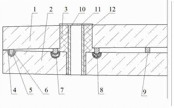
[0045] Example: see figure 1 , The convex vacuum glass is composed of an upper glass 1 and a lower glass 2, the periphery of the two pieces of glass is welded together by glass solder 4, and the middle is a vacuum layer. The production method is as follows: First, cut two pieces of flat glass according to the shape and size of the convex vacuum glass to be produced, and drill a through hole at the corner of the upper glass 1 and the lower glass 2 as the air inlet (installation hole) 3, Set up a sealing groove 6 around the periphery of the lower glass 2 and corresponding to the air outlet 3, and perform edge grinding, chamfering, cleaning, and drying, and use mechanical spraying technology to prepare sealing strips at the peripheral welding of the upper glass 1 and the periphery of the air outlet 3 5. Use a dispensing machine to prepare supports 9 on the upper and lower glass, and then make a silver paste layer 8 on the sealing strip around the air inlet 3 and the surface of th...


PUM

PropertyMeasurementUnit
melting pointaaaaaaaaaa

Abstract

High-temperature-sheet-combination convex vacuum glass provided with edges sealed by sealing grooves and provided with mounting hole(s) is disclosed. The convex vacuum glass comprises upper glass and lower glass, and is characterized in that: each mounting hole and a corresponding air extracting hole are of an integrated structure; the number of the mounting hole(s) is 1-4; peripheries of the upper glass and each air extracting hole are provided with sealing strips; corresponding positions of the periphery of the lower glass and each air extracting hole are provided with the sealing grooves; after being rapidly heated, the upper glass and the lower glass are subjected to sheet combining at a high temperature, and peripheries of the upper glass and the lower glass are welded under elevated pressure by glass solder in a heating furnace; each air extracting hole is automatically sealed by utilization of metal solder in a vacuum furnace; and a sealed vacuum layer is formed between the upper glass and the lower glass. The vacuum glass and a manufacturing method thereof are simple in process and high in production efficiency. The manufactured vacuum glass eliminates edge sealing stress and maintains tempered characteristics of tempered glass. Tempered vacuum glass can be produced in a large scale, and the service lifetime of the tempered vacuum glass can be prolonged.

Description

technical field [0001] The invention relates to the technical field of glass deep processing, in particular to a convex vacuum glass with mounting holes on the sealing edge of a high-temperature laminated sealing groove and a manufacturing method thereof. Background technique [0002] As a new type of glass with the most energy-saving potential, vacuum glass has achieved large-scale production after more than ten years of research and development, and has been well applied in many fields, especially in the construction field; but there are also obvious The shortcomings are mainly low production efficiency, small production capacity, and inability to produce tempered vacuum glass, etc., which limit its popularization and application in a wider range; the existing large-scale production of vacuum glass uses high temperature (430-480°C) normal pressure The production process of lower edge sealing, low temperature (180-300°C) vacuuming and sealing, because it needs to be kept wa...

Claims


Application Information

Patent Timeline
Patent Type & Authority Applications(China)
IPC IPC(8): C03B23/24C03C27/08
CPCY02P40/57
Inventor 戴长虹
Owner 戴长虹
Why Eureka
Try Eureka