Electric hydraulic multifunctional grab bucket

A multi-functional, hydraulic technology, applied in mechanically driven excavators/dredgers, earthmovers/shovels, construction, etc., it can solve the problem of inability to grab the garbage in the garbage pond and the leachate at the bottom of the garbage pond cannot be cleaned out. And other issues

Inactive Publication Date: 2015-07-01
上海佩纳沙士吉打机械有限公司
View PDF5 Cites 3 Cited by
  • Summary
  • Abstract
  • Description
  • Claims
  • Application Information

AI Technical Summary

Problems solved by technology

[0004] In view of the above problems, the present invention provides an electro-hydraulic multifunctional grab to solve the problem that the multi-lobe electro-hydraulic grab in the prior art cannot grab the garbage around the garbage pool, and the leachate at the bottom of the garbage pool cannot pass through the garbage pool. The problem of cleaning out the multi-lobed electro-hydraulic grab

Method used


Image

  • Electric hydraulic multifunctional grab bucket
  • Electric hydraulic multifunctional grab bucket
  • Electric hydraulic multifunctional grab bucket

Examples


Embodiment Construction

[0020] In order to make the technical means, creative features, objectives and effects achieved by the present invention easy to understand, the present invention will be further described below in conjunction with specific embodiments.

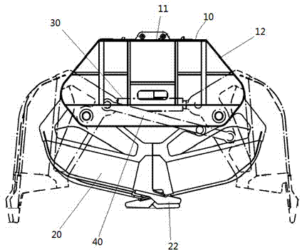
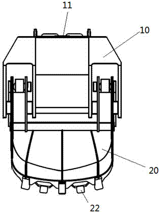
[0021] see figure 2 , 3 , 4. The electro-hydraulic multifunctional grab mainly includes an upper bolster 10, a hydraulic system, a double-lobe bucket body 20, and a horizontal oil cylinder 30 for driving the double-lobe bucket body to move.

[0022] The upper bolster 10 is a sealed box-type upper bolster, and a sealing plate 11 is arranged on the top of the upper bolster, and side plates 12 are respectively arranged on the left and right sides, and the front and rear sides of the upper bolster; the hydraulic system (not shown in the figure) It is installed inside the sealed box-type upper bolster to ensure that the grab can work normally under 5 meters of water. The detachable connection between the sealing plate 11 and the upper bolster 1...


PUM


Abstract

The invention discloses an electric hydraulic multifunctional grab bucket. The grab bucket comprises an upper bearing beam, a hydraulic system, a bivalve bucket body and a horizontal oil cylinder used for driving the bivalve bucket body to act, wherein the two ends of the horizontal oil cylinder are connected with the bivalve bucket body, the horizontal oil cylinder is connected with the hydraulic system, and cutting edges of the bivalve bucket body are of tooth-shaped structures arranged in a staggered mode and matched. As the bivalve bucket body structure is adopted, and the tooth-shaped structures are arranged on the cutting edges of the bivalve bucket body, all regions in a waste storage tank can be cleared conveniently, and percolate at the bottom of the waste storage tank can be cleared.

Description

technical field [0001] The invention relates to an electro-hydraulic grab bucket, which is mainly applicable to the domestic garbage power generation industry. In addition to grabbing the domestic garbage in the garbage storage pool, it can also grab the garbage in the garbage leachate and the corner materials of the garbage pool. Background technique [0002] In the past, the waste-to-energy industry used multi-lobe electro-hydraulic grabs to grab domestic waste and throw it into the furnace for incineration. However, due to the high water content in the waste, a large amount of leachate will be produced during the stacking and fermentation period. The bottom of the waste pool itself is designed with drainage However, the silt produced in the garbage will quickly block the leaking holes, resulting in too high a pool of leachate at the bottom of the pool, and the new garbage is not easy to stack and reduces the combustion value of the garbage. If the leachate cannot be disch...

Claims


Application Information

Patent Timeline
Patent Type & Authority Applications(China)
IPC IPC(8): E02F9/00E02F9/22E02F3/60E02F5/28
Inventor 刘爱峰沈怡
Owner 上海佩纳沙士吉打机械有限公司
Why Eureka
Try Eureka