[0028] In order to further illustrate the superiority of this device, the performance of this device is tested with different data:
[0029] The first group: For the same slurry, different pump bodies with the same power are used, and the pressure, single use cycle, power per unit time, height and horizontal distance are tested respectively. The experimental data obtained are shown in the following table:
[0030] .
[0031] Note: The same slurry is pure foam concrete slurry, but also other fine materials, slurries, etc.
[0032] It can be seen from the above table that the pump body of the same power transports the same slurry. The conveying height and conveying distance of this device far exceed the diaphragm pump and hose pump, and its power per unit time reaches 50 cubic meters. Hourly, it is far greater than the unit time power of the diaphragm pump and the hose pump; it can be seen from the table that the single maintenance cycle of the device can reach 8000 cubic meters, while the hose pump and the diaphragm pump are only 300 and 500 cubic meters.
[0033] The second group: For the same device, use different materials of piston rings and lubrication methods to test the sealing period (continuous working time):
[0034] .
[0035] It can be seen from the above table that the use of different piston rings will greatly affect the sealing cycle. However, even if the same piston ring is used in this device, if the arrangement is different, the sealing cycle will be seriously affected.
[0036] The third group: For the same device, the structure of the sealing ball and the feed valve/discharge valve is compared with the structure without the structure, and the structure is used to test the pressure generated by the seal. Continuous cycle
[0037] ,
[0038] Analysis of the above table shows that this device adopts PTFE in the sealing ball and the feed valve/discharge valve, so that it can obtain a large pressure. The structure without the PTFE layer only obtains 6 -8MPa pressure. However, even if the same structure is used, the sealing ball center of the device is not used to deviate from the center line of the connecting pipe. The accumulation of materials makes the pressure continuous cycle greatly reduced. The analysis of the reasons shows that the sealing of the device When the ball is in or out of the material, the sealing ball is rotated and fed, so that the material is not easy to stick to the contact surface of the sealing ball and the inner cavity of the valve, ensuring the sealing cycle.
[0039] The present invention will be further explained below in conjunction with the drawings:
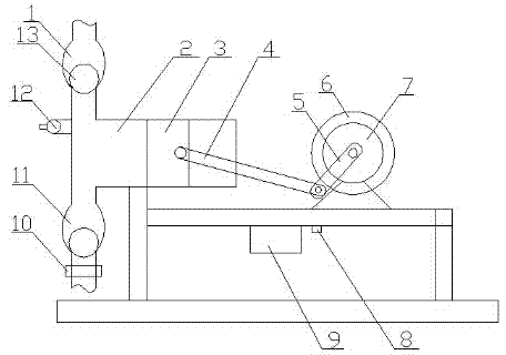
[0040] Such as Figure 1-6 Shown: a conveying device for foamed concrete, comprising a driving mechanism, a pump body and a control mechanism, the driving mechanism is connected with the pump body, and the book control mechanism and the driving mechanism are signal interconnected with the pump body.
[0041] The drive mechanism includes a drive motor 7, a flywheel 6, a crank 5, and a connecting rod 4. The drive motor 7 is connected to a crank 5, the crank 5 is connected to the flywheel 6, and the crank 5 is movably connected to the connecting rod 4. .
[0042] The pump body includes a cavity 2, a piston 3, a feed valve 11 and a discharge valve 1. The cavity 2 is provided with a piston 3, and the upper part of the front end of the cavity 2 is provided with a discharge valve 1, and the cavity 2 A feed valve 11 is provided at the lower part of the front end, and a sealing ball 13 is provided in the upper part of the feed valve 11 and the discharge valve 1.
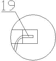
[0043] The control mechanism includes a PLC9, a pressure sensor 12, a flowmeter 10, a frequency converter 8 and a wear sensor 19, and the PLC9 is connected to the pressure sensor 12, the flowmeter 10, the frequency converter 8 and the wear sensor 19 respectively.
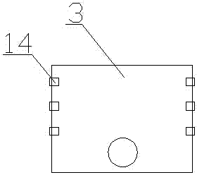
[0044] The pressure sensor 12 is arranged at the cavity 2, the flow meter 10 is arranged at the feed valve 11, the frequency converter 8 is connected to the driving motor 7, and the wear sensor 19 is arranged in the piston ring 14.
[0045] The sealing ball 13 is a steel ball with a polytetrafluoroethylene coating 15 attached to the surface.
[0046] The feed valve 11 includes a valve body 20, a feed connection pipe 17 and a discharge connection pipe 16. The feed connection pipe 17 is connected to the discharge connection pipe 16 through the valve body 20, and the valve body 20 is an inner The cavity is ellipsoidal, and the feeding connecting pipe 17 is deviated from the center line of the long axis of the valve body 20.
[0047] The inner cavity of the valve body 20 is provided with a polytetrafluoroethylene coating film 18.
[0048] The number of the piston ring 14 is three, and the piston ring provided in the middle is a graphite ring.
[0049] The flow meter 10 is arranged at the feed connection pipe 17.
[0050] The invention adopts a mechanical cylinder pushing method to replace the existing diaphragm pump or hose pump, not only the structure becomes compact, but also the efficiency is greatly improved; the feed valve and the discharge valve are respectively arranged in the cavity The front end of the body is distributed up and down. Sealing balls are arranged inside the feeding valve and the discharging valve. Due to the gravity of the sealing ball, when the piston is sucking materials, the negative pressure is generated in the cavity due to the gas pressure. The gravity of the material valve sealing ball and the downward adsorption of negative pressure can firmly adsorb the sealing ball at the discharge valve, and the negative pressure and atmospheric pressure generated in the cavity make the sealing ball at the inlet valve roll upwards , So that the material is sucked into the cavity by the action of air pressure; when the piston moves in the cavity to the maximum value of the cavity, the cavity is filled with material. At this time, the piston is compressed by the driving mechanism. Exclude the material outside, because the material squeezes the sealing ball at the feed valve, the sealing ball plus its own gravity can firmly seal the feed valve, and the sealing ball at the discharge valve is under the pressure of the material, so It breaks through the gravity of the sealing ball, thereby expelling the material outward. When the piston is compressed to empty the material, it re-enters the suction material and circulates in turn.
[0051] The feed valve and the discharge valve are of the same structure. The inner cavity of the valve is of ellipsoidal structure. Take the feed valve as an example. When the piston sucks material, negative pressure is generated in the cavity, and the atmospheric pressure pushes the sealing ball upward Movement, when the atmospheric pressure minus the negative pressure value exceeds the gravity, the sealing ball rolls upwards; thus, the material enters the inner cavity of the feed valve. Because of the ellipsoidal inner cavity, when the sealing ball rolls upwards, the inner cavity space becomes larger. The material easily passes through the sealing ball and enters the cavity. The sealing ball is a steel ball with a PTFE coating on the surface, so that it can not only prevent the steel ball from rusting but also reduce the friction between the sealing ball and the material while ensuring the weight The sealing ball keeps smooth and clean at all times and does not stick to the material to ensure the sealing effect; and the PTFE in the cavity of the valve body can ensure the smoothness of the inner wall and prevent the sticking of the material, and its cooperation with the sealing ball can ensure The effect of sealing.
[0052] The valve bodies of the inlet valve and the outlet valve are ellipsoidal, and the inlet connecting pipe and the inner cavity of the valve deviate from the center line of the long axis. When feeding, the thrust applied by the material to the sealing ball deviates from the center surface of the sealing ball. Applied, this kind of structure allows the material to break through the gravity seal of the sealing ball with only a small amount of power when feeding, but it does not affect the pressure and sealing of the sealing ball on the valve body, and this way increases the material passing through the valve. The smoothness of the sealing ball makes the contact surface of the sealing ball and the inner cavity of the valve keep clean under the action of the rotation of the sealing ball, so that it can be well sealed when sealing is needed, avoiding the phenomenon of lax sealing, and due to poly The characteristics of tetrafluoroethylene can ensure non-sticky materials, good lubrication and good toughness.
[0053] The driving mechanism adopted includes a driving motor, a crank, a flywheel and a connecting rod. The driving motor is connected to the crank spindle through a belt drive or a chain drive, and the crank spindle is connected to the flywheel, which can stabilize the rotation speed of the crank so that the connecting rod can be When connected with the crank, it can easily pass through the dead point to ensure the stability of the system. At the same time, when the connecting rod and the piston are connected, the crosshead can be used as a transition to ensure the stable operation; at the same time, the inverter in the control mechanism is used to drive the motor Perform control to adjust the speed of the drive motor, and then adjust the power of the system.
[0054] A pressure sensor is installed in the device to detect the pressure in the cavity, and a flow meter is installed at the feed valve to monitor the volume of the feed in real time. A certain amount of material can be set, or it can be set to feed every hour. How much, it’s very easy to operate; when the piston ring wears to a certain extent, the wear sensor can be used to send an alarm through the PLC to remind the staff to replace it in time. It adopts the form of a three-layer piston ring with a graphite piston in the middle. Ring, which can lubricate the inner wall of the cavity to prolong the service life of the piston ring and the cavity; the wear sensor used is a conventional wear sensor. When the wear reaches a certain level, the wire is worn and disconnected, and the signal is cut off to send an alarm ; Set it in the graphite piston ring, because the graphite piston ring wears faster than the rigid piston ring, so that when it wears and loses its lubricity, it can promptly issue an alarm to remind the replacement of the graphite piston ring to ensure the safe and stable operation of the device.
[0055] The invention adopts a mechanical cylinder pushing method, so that the pressure can be increased to 7-9MPa, and the conveying height is increased from the original 120 meters to more than 250 meters, and the structure is simple and the operation is simple, and the single maintenance service life can be It can reach 8,000 cubic meters, and the maintenance is simple, which reduces the pain of maintenance personnel. Moreover, the device can not only transport slurry but also transport mortar, ceramic slurry and small stone slurry, etc.; it also avoids the sand and stone caused by existing equipment Phenomena such as sedimentation, stratification and solid drum are worthy of promotion and application.