Energy-saving chimney of thermal power plant

A technology for thermal power plants and chimneys, applied in the field of chimneys, can solve the problems of environmental pollution and low resource utilization, and achieve the effects of reducing pollution, improving efficiency, and reducing particulate matter.

Inactive Publication Date: 2015-07-01
常熟市第二热电有限公司
View PDF10 Cites 0 Cited by
  • Summary
  • Abstract
  • Description
  • Claims
  • Application Information

AI Technical Summary

Problems solved by technology

If the flue gas containing a lot of heat is directly discharged, the heat in the flue gas will not only pollute the environment, but also the resource utilization rate is not high

Method used


Image

  • Energy-saving chimney of thermal power plant

Examples


Embodiment Construction

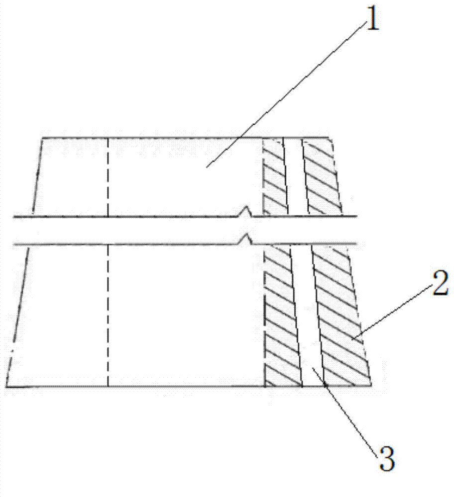
[0013] A kind of energy-saving chimney of thermal power plant, such as figure 1 As shown, the chimney wall 2 is formed into a cylindrical shape, and a flue 1 is formed inside the chimney wall 2. An interlayer 3 is arranged between the outer surface and the inner surface of the chimney wall 2, and the interlayer 3 is filled with water.

[0014] The heat carried by the flue gas exchanges heat with the water in the interlayer 3 through the chimney wall 2 to improve heat utilization efficiency. At this time, the thickness of the interlayer 3 and the inner side of the chimney wall 2 should be appropriate, otherwise the heat exchange efficiency will be reduced. In order to properly prolong the residence time of the flue gas in the flue 1 and improve the heat exchange efficiency, the flue 1 is spiral.

[0015] Likewise, in order to improve the heat exchange efficiency, the interlayer 3 is divided into helical flow channels.

[0016] The chimney of the invention can effectively exch...


PUM


Abstract

The invention discloses an energy-saving chimney of a thermal power plant. The energy-saving chimney is tubular and composed of a chimney wall, a flue is formed on the inner side of the chimney wall, an interlayer is arranged between the outer side and the inner side of the chimney wall and is filled with water, and smoke heat exchanges heat with water in the inner layer via the chimney wall. Heat contained in the smoke can be effectively exchanged, energy utilization efficiency is improved, particles in the smoke after heat exchange can be reduced and resultantly air pollution is alleviated.

Description

technical field [0001] The invention relates to a chimney, in particular to an energy-saving chimney, which can be used in thermal power plants and other factories and mines. Background technique [0002] Cogeneration enterprises are well-known energy-saving enterprises at home and abroad, but at the same time they are large energy consumers. Thermal power plants mainly provide heat, and electricity is a by-product. Thermal power plants supply more heat to save more energy and increase benefits. Therefore, many shrewd factory managers do everything possible to extend the heating network, expand the heating range, increase the heat supply, and seize the heating market. Such measures not only reduce coal consumption for power generation and heating, but also improve the economic benefits of enterprises. However, in the work of extending the heating network, it is necessary to pay attention to the efficient use of heat while ensuring the quality of heat supply. [0003] The...

Claims


Application Information

Patent Timeline
Patent Type & Authority Applications(China)
IPC IPC(8): F23J11/00F23J15/06
CPCY02E20/30
Inventor 方建文
Owner 常熟市第二热电有限公司
Why Eureka
Try Eureka