

Reference voltage generating circuit and reference voltage calibrating method
- Summary
- Abstract
- Description
- Claims
- Application Information
AI Technical Summary
Problems solved by technology
Method used
Image

Examples
Embodiment 1
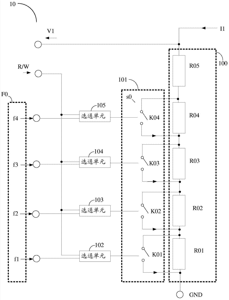
[0068] Such as image 3 A reference voltage generation circuit 10 shown includes a resistor unit 100, a switch unit 101 and a gating unit (102 to 105). The reference voltage generating circuit 10 of this embodiment only includes one resistor unit 100 .
[0069] The resistance unit 100 includes a plurality of series resistance elements ( R01 to R05 ), and the resistance unit 100 is suitable for outputting a reference voltage V1 according to the input current I1 and the output resistance. The reference voltage V1 is the product of the output resistance and the input current I1. When the output resistance matches the input current I1, the reference voltage V1 obtained at this time is the matching voltage of the resistance unit.
[0070] The input current I1 is composed of a first partial current with a positive temperature coefficient and a second partial current with a negative temperature coefficient. It can be considered that the input current I1 is the sum of the first parti...
Embodiment 2
[0090] This embodiment is based on embodiment 1, provides a kind of such as Figure 4 The difference between the shown reference voltage generation circuit 20 and Embodiment 1 lies in:
[0091] The switch element is realized by a switch transistor;
[0092] The reference voltage generation circuit 20 further includes a current unit 106 adapted to provide the input current I1. refer to Figure 4 , the current unit 106 includes: a current mirror unit 61, an operational amplifier unit 62, a first resistor 63, a second resistor 64, a third resistor 65, a first bipolar transistor T1 and a second bipolar transistor T2;
[0093] The current mirror unit 61 includes a first node 610, a second node 611, a first PMOS transistor P1, a second PMOS transistor P2, and a third PMOS transistor P3, and the first PMOS transistor P1, the second PMOS transistor P2, and the third PMOS transistor The gate of the transistor P3 is connected to the first node 610, the source is connected to the second...
Embodiment 3
[0110] This embodiment provides a Figure 5 The shown reference voltage generation circuit 30 is based on the reference voltage generation circuit described in Embodiment 1, and further includes the current unit 106 described in Embodiment 2.
PUM
 Abstract
Description
Claims
Application Information