Optical waveguide type fingerprint identifying system based on grating structure

A technology of fingerprint identification and optical waveguide, which is applied in character and pattern recognition, instruments, computer components, etc., can solve the problems of large reflection of optical path, difficulty in miniaturization, and low imaging quality, and achieve large image acquisition area and precise optical path Effects that control and enhance image quality

Active Publication Date: 2015-07-01
SHANGHAI JIAO TONG UNIV
View PDF7 Cites 76 Cited by
  • Summary
  • Abstract
  • Description
  • Claims
  • Application Information

AI Technical Summary

Problems solved by technology

The traditional optical fingerprint recognition system generally has three disadvantages: 1. The structure is complex and difficult to miniaturize; 2. The optical path is greatly affected by the diffuse reflection of the finger, and the imaging quality is not high; 3. Using the sliding fingerprint scanning method, the user experience is relatively poor. Poor; U.S. Patent US5177802 discloses a structure that uses prisms to read fingerprint images, but this structure is difficult to miniaturize due to the use of prisms, and cannot be used in mobile terminals such as smart phones and tablet computers
Chinese patent CN1820272A discloses a system that uses an optical waveguide structure to realize fingerprint image reading, but the optical path of this structure is relatively rough, the imaging quality is poor, and the optical waveguide structure is relatively thick, making it difficult to achieve ultra-thinning
U.S. Patent US6259108B1 discloses a structure that uses a linear array CCD for sliding fingerprint scanning, but the overall structure is large and difficult to miniaturize

Method used


Image

  • Optical waveguide type fingerprint identifying system based on grating structure
  • Optical waveguide type fingerprint identifying system based on grating structure
  • Optical waveguide type fingerprint identifying system based on grating structure

Examples


Embodiment Construction

[0052] The present invention will be described in detail below in conjunction with the embodiments and accompanying drawings, but the protection scope of the present invention should not be limited thereby.

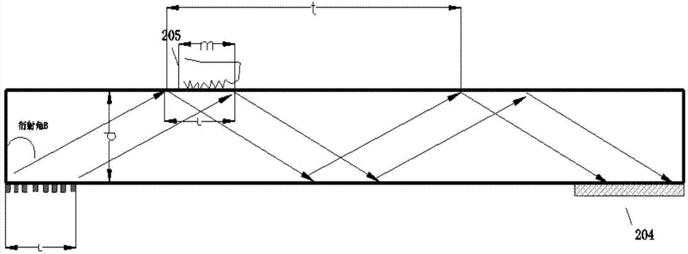
[0053] An optical waveguide fingerprint recognition system based on a grating structure, including a grating 201, which converts incident light from a light source into light for fingerprint detection that can propagate in the optical waveguide; an optical waveguide 202, which diffracts the light from the light source through the grating Afterwards, total reflection propagation can be carried out therein; detection area 205, the area where the finger touches and collects fingerprints; light source 203, which provides light for fingerprint collection; image sensor 204, the light from the light source enters the image sensor after being reflected by the finger to realize fingerprint imaging.

[0054] According to the grating diffraction equation T(n 1 sinθ±n 2sini)=kλk=0,±...


PUM


Abstract

The invention relates to an optical waveguide type fingerprint identifying system based on a grating structure. The optical waveguide type fingerprint identifying system comprises a light source, a grating, an optical wave-guider, a detection area and an image sensor, wherein the light source is used providing light for fingerprint acquisition, the grating is used for converting incident light of the light source into a waveguide die propagated in the optical waveguide for fingerprint detection, and the optical waveguide is used for propagating and carrying out total reflection light of the light source after being diffracted by the grating; the detection area is used for being in contact with a fingerprint to realize fingerprint acquisition, and the image sensor is used for enabling the light of the light source being reflected by the finger to enter the image sensor to realize fingerprint imaging. The optical waveguide type fingerprint identifying system is characterized in that a grating structure is used when the light source enters a light path of the optical wave-guider so that the light in the optical wave-guider is diffracted to form fingerprint detection light, and then is received to a fingerprint image which is not subject to aliasing by a sensor, so as to significantly reduce, realize periodic area fingerprint acquisition and touch control, realize the miniature and ultrathin of the system, and effectively the imaging quality at the same time.

Description

technical field [0001] The invention relates to the technical field of optical fingerprint imaging, in particular to an optical waveguide fingerprint identification system based on a grating structure. Background technique [0002] Fingerprint identification technology can be classified into three categories: optical, capacitive, and radio frequency, according to the way of fingerprint image collection. When the finger touches, the corresponding sensor detects the corresponding physical quantity and converts it into an electrical quantity to form a fingerprint image for comparison and identification. [0003] The capacitive fingerprint identification system uses the sensor as one pole of the capacitor, and the finger as the other pole. The difference in the position of the ridge and valley of the finger fingerprint relative to the plate forms a capacitance difference, which is detected to form a fingerprint image. The radio frequency fingerprint identification system transm...

Claims


Application Information

Patent Timeline
Patent Type & Authority Applications(China)
IPC IPC(8): G06K9/00
Inventor 叶志成崔雪成洪芃力
Owner SHANGHAI JIAO TONG UNIV
Why Eureka
Try Eureka