Motor with thrust bearing

A technology of thrust bearings and motors, applied in the field of motors, can solve the problems affecting the smooth rotation of the rotor 93 and the increase of frictional resistance

Active Publication Date: 2015-07-01
SUNONWEALTH ELECTRIC MACHINE IND
View PDF7 Cites 5 Cited by
  • Summary
  • Abstract
  • Description
  • Claims
  • Application Information

AI Technical Summary

Problems solved by technology

[0003] When the rotor 93 of the conventional motor 9 described above rotates relative to the thrust bearing 912, since the opposing surfaces of the thrust plate 913 and the thrust bearing 912 are attached to each other, the thrust plate 913 and the thrust bearing 912 are in contact with each other. The contact portion of the thrust bearing 912 is in a "completely attached" state (such as figure 1 F shown), during the rotation of the rotor 93, the frictional resistance between the thrust plate 913 and the thrust bearing 912 increases, which easily affects the smooth rotation of the rotor 93, so it is necessary to improve

Method used


Image

  • Motor with thrust bearing
  • Motor with thrust bearing
  • Motor with thrust bearing

Examples


Embodiment Construction

[0054] In order to make the above-mentioned and other objects, features and advantages of the present invention more comprehensible, the preferred embodiments of the present invention are specifically cited below, together with the accompanying drawings, as follows:

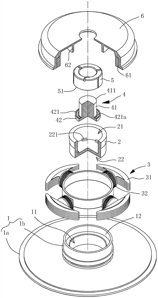
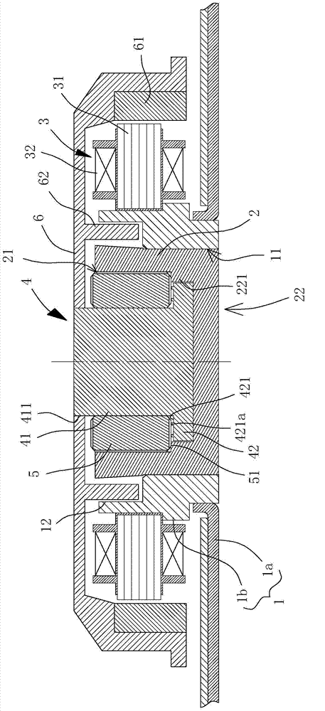
[0055] Please refer to figure 2 and 3 As shown, the motor with thrust bearing of the present invention at least includes a base 1 , a bearing sleeve 2 , a stator 3 , a rotating member 4 , a thrust bearing 5 and a hub 6 . The bearing sleeve 2 and the stator 3 are combined with the base 1 , the rotating member 4 and the thrust bearing 5 are combined inside the bearing sleeve 2 , and the hub 6 is combined with the rotating member 4 .

[0056] Above-mentioned base 1 is provided with a joint portion 11, and this joint portion 11 can be various structural designs that can be combined with above-mentioned bearing sleeve 2; figure 2 In the illustrated embodiment, the base 1 may include a base plate 1a and a sleeve 1b...


PUM


Abstract

A motor includes: a bearing sleeve arranged with a base and having opposite opening and sealing ends; a stator coupled with the base or bearing sleeve; a rotating member disposed in the bearing sleeve and comprising a shaft and a limiting portion adjacent to the sealing end, wherein a first end of the shaft connects with the limiting portion, a second end of the shaft has a coupling portion, and the limiting portion has a first contact surface; a thrust bearing arranged between the shaft and the bearing sleeve and having a second contact surface facing the first contact surface, wherein at least one of the first and second contact surfaces is an uneven surface; a hub coupled with the coupling portion of the shaft and having a permanent magnet corresponding to the stator.

Description

technical field [0001] The present invention relates to a motor with a thrust bearing, especially a motor capable of stable rotation. Background technique [0002] Please refer to figure 1 As shown, the conventional motor 9 with a thrust bearing includes a bracket 91 , a stator 92 and a rotor 93 . The bracket 91 is combined with a bearing housing 911. A thrust bearing 912 and a thrust plate 913 are arranged inside the bearing housing 911. The opposite ends of the bearing housing 911 each have an opening, one of which is open for the rotor 93. Combining, the other end opening is combined with a cover 914; the stator 92 is combined with the outer peripheral wall of the bracket 91; the rotor 93 has a hub 931, and the hub 931 integrally forms a ring flange 932 and is provided with a rotating shaft 933, the ring The flange 932 is located between the bracket 91 and the bearing housing 911 to provide functions such as dust-proof or oil-proof. The rotating shaft 933 extends into t...

Claims


Application Information

Patent Timeline
Patent Type & Authority Applications(China)
IPC IPC(8): H02K5/16
CPCH02K7/088F16C41/004H02K5/10F16C17/04F16C17/107F16C33/106F16C43/02F16C2370/12G11B19/2009H02K5/1675H02K7/085H02K2205/03
Inventor 洪银树
Owner SUNONWEALTH ELECTRIC MACHINE IND
Why Eureka
Try Eureka