Motor rotor assembling process

An assembly process and motor rotor technology, applied in the manufacture of stator/rotor body, etc., can solve problems such as loss of magnetization, termination of stator and rotor, and loss of permanent magnets, so as to improve performance and life, avoid excessive temperature rise, and prevent foreign matter from entering Effect

Inactive Publication Date: 2015-07-01
HUBEI HUITONG MOTILITY IND CO LTD
View PDF5 Cites 3 Cited by
  • Summary
  • Abstract
  • Description
  • Claims
  • Application Information

AI Technical Summary

Problems solved by technology

[0002] At present, the manufacture of high-speed rotors by most manufacturers adopts the method of directly gluing the magnetic tiles on the rotor core. Since the permanent magnet part and the rotor core are glued together, the permanent magnet part is exposed outside the rotor. , this structure bonds the permanent magnets to the surface of the rotor core by gluing, it is difficult to ensure the firmness and position, and the adhesive colloid is likely to cause colloidal damage due to the long-term operation of the motor and the different use environments Loss of function, causing the permanent magnet part to fall off
In addition, during the coating process of the colloid, it is difficult to control the thickness of each part, so it is likely to cause excessive dimensional error after the permanent magnet part is bonded and formed, resulting in the phenomenon of bore sweeping, which eventually leads to permanent magnet rupture or excessive friction temperature. irreversible demagnetization
Another method is to bind the permanent magnets together with insulating binding tape, which brings more problems, because the binding tape is made of plastic material, which is easy to soften at high temperature, resulting in loosening, and once loosened, it is likely to cause fixed magnets. The relative movement of the rotor is terminated, that is, the phenomenon of jamming

Method used


Image

  • Motor rotor assembling process

Examples


Embodiment Construction

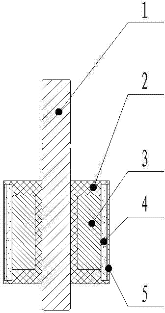
[0011] The assembly of the motor rotor of the present invention adopts a special tooling fixture, and the rotor iron core 3 is fixed in the middle of the fixture, and the aluminum ring 5, which can also be a stainless steel ring, is fixed on the fixture, and the rotor core 3 is guaranteed by the fixture. The concentricity with the aluminum ring 5, because the rotor core 3 is formed by high-speed stamping superposition or precision machining, and the aluminum ring 5 is formed by precision stretching, so the matching dimensions of the rotor core 3 and the aluminum ring 5 The tolerance can be controlled within a relatively small precision range, for example: the tolerance of the outer diameter of the rotor core 3 is φ25-0.015mm, and the tolerance of the inner diameter of the aluminum ring 5 is φ29-0.02mm. After the rotor core 3 and the aluminum ring 5 are fixed by the fixture, the concentricity can be guaranteed, basically within the tolerance range of 0.05mm. After the magnetic ...


PUM


Abstract

The invention discloses a motor rotor assembling process, relates to the assembling process of a motor rotor and mainly solves the problems that magnetic shoe adhesive is adhered to the rotor iron core directly and currently and the stability and position are difficult to guarantee. The process includes a, adopting a special tooling fixture to fix a rotor iron core in the middle of the fixture, fixing an aluminum ring to the fixture, and guaranteeing the concentricity of the rotor iron core and aluminum ring; b, adopting a pressing fixture to press a magnetic shoe between the rotor iron core and aluminum ring with the controlled concentricity, and allowing the magnetic shoe to fit to the external circle of the rotor iron core and the internal circle of the aluminum ring; c, integrating a rotor shaft and a magnetizer conductor composed of the rotor iron core, the magnetic shoe and the aluminum ring through an injection molding part in an injection molding manner; d, turning the external circle of the permanent magnetic rotor through a lathe after injection molding, performing dynamic balancing, adjusting the dynamic balancing scale by the material increasing method, and achieving the design requirements. The process has the advantages of high efficiency, fine performances and long service life.

Description

technical field [0001] The invention relates to a motor rotor, in particular to an assembly process of the motor rotor. Background technique [0002] At present, the manufacture of high-speed rotors by most manufacturers adopts the method of directly gluing the magnetic tiles on the rotor core. Since the permanent magnet part and the rotor core are glued together, the permanent magnet part is exposed outside the rotor. , this structure bonds the permanent magnets to the surface of the rotor core by gluing, it is difficult to ensure the firmness and position, and the adhesive colloid is likely to cause colloidal damage due to the long-term operation of the motor and the different use environments Loss of function, so that the permanent magnet part falls off. In addition, during the coating process of the colloid, it is difficult to control the thickness of each part, so it is likely to cause excessive dimensional error after the permanent magnet part is bonded and formed, re...

Claims


Application Information

Patent Timeline
Patent Type & Authority Applications(China)
IPC IPC(8): H02K15/03
Inventor 李胜
Owner HUBEI HUITONG MOTILITY IND CO LTD
Why Eureka
Try Eureka