Brushless motor and control method thereof

A brushless motor, feedback control technology, applied in the direction of electronic commutation motor control, control system, electrical components, etc., can solve the problems of reducing the efficiency of the whole machine, large commutation influence, etc., to prolong the life of the motor and eliminate errors.

Inactive Publication Date: 2015-07-01
NANJING CHERVON IND
View PDF6 Cites 7 Cited by
  • Summary
  • Abstract
  • Description
  • Claims
  • Application Information

AI Technical Summary

Problems solved by technology

In the case of sensor control, full torque start can be achieved, but there are installation errors, especially for motors with many pole pairs running at high speed, which will have a great impact on commutation and reduce the efficiency of the whole machine

Method used


Image

  • Brushless motor and control method thereof
  • Brushless motor and control method thereof

Examples


Embodiment Construction

[0021] The present invention will be specifically introduced below in conjunction with the accompanying drawings and specific embodiments.

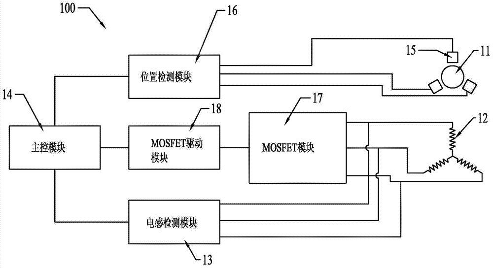
[0022] refer to figure 1 As shown, the brushless motor 100 of the present invention includes: a rotor 11, three sets of stator windings 12, a position detection module (not marked in the figure, the same below), a MOSFET component (not marked in the figure, the same below), an inductance detection module 13 and a control Their main control module 14 .

[0023] Wherein, the position detection assembly includes: 3 detection elements 15 capable of detecting the position of the rotor, and a position detection module 16 capable of receiving feedback signals from the detection elements. The position detection module 16 is electrically connected to the main control module 14 and feeds back the position of the rotor 11 to it. location information.

[0024] The inductance detection modules 13 are respectively electrically connected to the stator...


PUM


Abstract

A brushless motor includes a rotor, a plurality of sets of stator windings, a position detection assembly, a MOSFET assembly, an inductance detection module and a main control module that controls them. The position detection assembly has a plurality of detection elements for detecting a position of the rotor and a position detection module for receiving signals fed back from the detection elements with the position detection module being electrically connected to the main control module and feeding back the positional information of the rotor thereto. The main control module alternatively switches between the position detection assembly and the inductance detection module to detect the position of the rotor. When the motor runs at a low speed, the system may effectively judge the position of the rotor to enable the machine to start with a load and, when the motor runs at a high speed, the system may accurately judge the position of the rotor, correctly drive the motor to run, eliminate errors caused by assembly, and prolong the service life of the motor.

Description

technical field [0001] The invention relates to a brushless motor and a control method thereof, in particular to a brushless motor with two detection modes and a control method thereof. Background technique [0002] The key to the control of the brushless DC motor is to detect the rotor position, and then obtain the commutation point according to the position information, and the corresponding stator winding is turned on and commutated, and the conduction current is synchronized with the back electromotive force of the winding. For power tools, most applications require full torque starting. In the case of sensor control, full torque start can be achieved, but there are installation errors, especially for motors with many pole pairs operating at high speeds, which have a greater impact on commutation and will reduce the efficiency of the whole machine. Contents of the invention [0003] In order to solve the deficiencies of the prior art, the purpose of the present inven...

Claims


Application Information

Patent Timeline
Patent Type & Authority Applications(China)
IPC IPC(8): H02P6/16
CPCH02P6/181H02P6/18H02P6/16H02P6/182H02P6/17
Inventor 杨德中杜浩石平波吴南飞
Owner NANJING CHERVON IND
Why Eureka
Try Eureka