Check patentability & draft patents in minutes with Patsnap Eureka AI!

Alkaline storage cell

A storage battery, alkaline technology, applied in the field of alkaline storage batteries, to achieve the effects of improving manufacturing efficiency, suppressing heat generation, and easy miniaturization

Inactive Publication Date: 2015-07-01
FDK CORP
View PDF5 Cites 0 Cited by
  • Summary
  • Abstract
  • Description
  • Claims
  • Application Information

AI Technical Summary

Problems solved by technology

As a result, batteries using a positive electrode lead incorporating a PTC thermistor are limited to larger batteries of AA size or larger.

Method used


Image

  • Alkaline storage cell
  • Alkaline storage cell
  • Alkaline storage cell

Examples


Embodiment approach 1

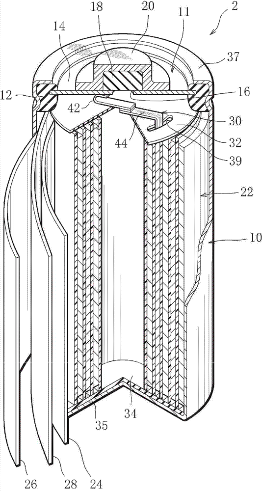
[0043] As the battery of Embodiment 1 to which the present invention is applied, for example, to apply the present invention to figure 1 The case of the shown AAA size cylindrical nickel-metal hydride storage battery (hereinafter referred to as battery) 2 will be described as an example.

[0044] Such as figure 1 As shown, the battery 2 has a bottomed cylindrical case 10 with an open upper end. The casing 10 is conductive, and its bottom wall 35 functions as a negative terminal. A sealing body 11 is fixed on the opening of the casing 10 . The sealing body 11 includes a cover plate 14 and a positive terminal 20 , and seals the case 10 and provides the positive terminal 20 . The cover plate 14 is a conductive disc-shaped member. A cover plate 14 and an annular insulating filler 12 surrounding the cover plate 14 are disposed in the opening of the housing 10 , and the insulating filler 12 is fixed to the opening edge 37 of the housing 10 by riveting the opening edge 37 of the ...

Embodiment approach 2

[0068] The battery of Embodiment 2 to which the present invention is applied will be described.

[0069] The battery of Embodiment 2 differs from the battery 2 of Embodiment 1 only in that the second overlapping end portion 82 including the second lead half body 80 is also provided with the positive electrode lead 31 embedded in the concave portion 84 . Therefore, members and parts that perform the same functions as those in Embodiment 1 that have already been described will be assigned the same reference numerals, their description will be omitted, and only the different points will be described.

[0070] First, if Image 6 As shown, the second lead half body 80 involved in the positive electrode lead 31 has a second embedding recess 84 on its second overlapping end portion 82 into which the PTC thermistor 40 can be embedded. The second fitting recess 84 has the same shape as the first fitting recess 70 provided in the first lead half body 42 . That is, the shape in plan vi...

Embodiment 1

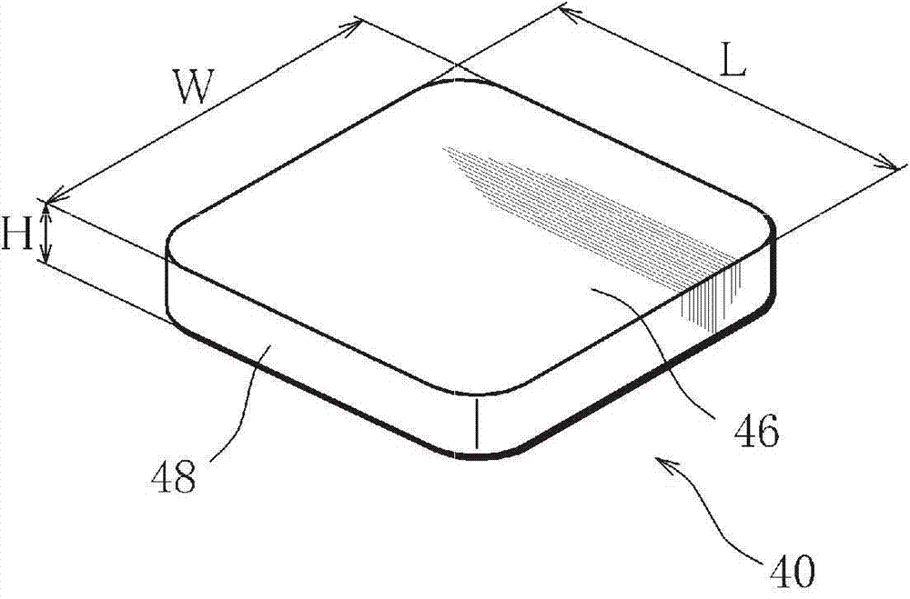
[0075] Such as image 3 As shown, a PTC thermistor 40 having a substantially rectangular plate shape with a length (L) of 3 mm, a width (W) of 3 mm, and a thickness (H) of approximately 1.0 mm and an operating temperature of 90° C. was prepared. In addition, the corners of the PTC thermistor 40 are formed in an arc shape.

[0076] On the other hand, as the first lead half body 42 and the second lead half body 44 , strip-shaped bodies made of nickel with a thickness of about 0.2 mm were prepared. These first and second lead halves 42, 44 are as Figure 4 As shown, it includes rectangular overlapping end portions 54, 56 having a length (L1) of 3.5 mm and a width (W1) of 3.5 mm, and body portions 62, 66 having a width (W2) of 3 mm. Further, between the overlapping end portions 54, 56 and the main body portions 62, 66, narrow portions 64, 68 having a width (W3) of 2.5 mm and a length (L2) of 1 mm are provided.

[0077] here, as Figure 4 , Figure 5 As shown, the overlapping ...


PUM

PropertyMeasurementUnit
surface temperatureaaaaaaaaaa
contact resistanceaaaaaaaaaa

Abstract

The present invention provides an alkaline storage battery including a positive electrode lead having a portion that incorporates a PTC thermistor, the portion being downsized so as to be placed in a smaller space than before, the alkaline storage battery being capable of suppressing heat generation on occasion of an external short circuit. A battery (2) includes a positive electrode lead (30), wherein the positive electrode lead includes a first lead half body (42), a second lead half body (44), and a PTC thermistor (40) disposed therebetween, the first lead half body and the second lead half body respectively have first and second overlap end portions (54, 56) formed in a portion where the first lead half body and the second lead half body overlap with each other, the overlap end portions being larger than the PTC thermistor as viewed from a plane and being in contact with the PTC thermistor, the PTC thermistor is fitted in a fitting recessed portion (70) formed in the overlap end portion of the first lead half body, and an exposed portion of the PTC thermistor which is not covered with the first and second overlap end portions is covered with a protective material (72).

Description

technical field [0001] The present invention relates to alkaline storage batteries. Background technique [0002] A general alkaline storage battery is produced in the following manner: After accommodating the electrode group composed of the positive electrode, the negative electrode, and the spacer in a case that doubles as the negative electrode terminal, injecting an alkaline electrolyte, and then sealing the battery with a sealing body. The upper end opening of the casing is sealed. The sealing body has a cover plate and a positive terminal electrically connected to the cover plate, and the cover plate is fixed to the upper end opening of the casing through an insulating filler. [0003] In such an alkaline storage battery, the negative electrode at the outermost peripheral portion of the electrode group is in contact with the inner wall of the case, and the negative electrode and the case (negative terminal) are electrically connected to each other. On the other hand,...

Claims


Application Information

Patent Timeline
Patent Type & Authority Applications(China)
IPC IPC(8): H01M10/28H01M2/26H01M2/34H01M50/184H01M50/538
CPCH01M2200/106Y02E60/124H01M10/345H01M2220/20H01M2/263H01M2/26H01M10/28H01M2/34H01M2/348H01M50/538H01M50/581H01M50/184H01M10/286H01M10/30Y02E60/10Y02P70/50H01M50/107H01M2220/30
Inventor 长井达也泉康士
Owner FDK CORP
Features
  • R&D
  • Intellectual Property
  • Life Sciences
  • Materials
  • Tech Scout
  • Unparalleled Data Quality
  • Higher Quality Content
  • 60% Fewer Hallucinations
Learn More