

Inner-outer-layered ball-milling device with forced axial flow and up-down circulation
A technology of axial flow and inner and outer layers, which is applied in the direction of grain processing, etc., can solve the problems of large vibration and noise, differences in grinding and refinement conditions, poor wear resistance, etc., and achieve the effect of convenient manufacturing and installation, convenient use, and large operating space
- Summary
- Abstract
- Description
- Claims
- Application Information
AI Technical Summary
Problems solved by technology
Method used
Image

Examples
Embodiment Construction
[0026] The present invention will be explained in detail below with reference to the accompanying drawings.
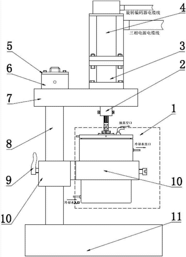
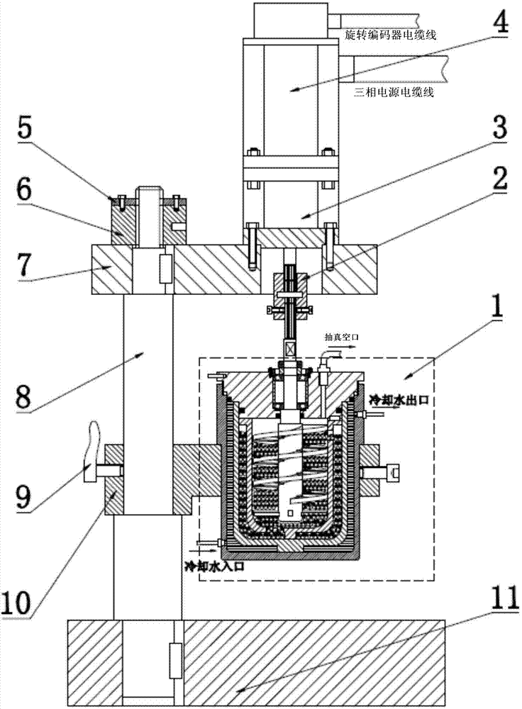
[0027] refer to figure 1 and figure 2 , a ball milling device with forced axial flow and up-and-down circulation on the inner and outer layers, comprising a multi-layer barrel-type ball mill cup 1, the ball mill cup 1 is connected to the swing arm 10, and there is a set on the outside of the outer layer barrel 1-2 of the ball mill cup 1 Shoulder, the ball mill cup 1 is placed in the ring hole of the swing arm 10 through the shoulder, and the side is fixed by a set screw, the swing arm 10 is connected on the column 8, the swing arm 10 is loaded from the upper side of the column 8, and the swing arm 10 and the weight of the ball mill cup 1 are borne by the shoulder on the column 8, the swing arm 10 can swing upward around the column 8, and the position is fixed by the nail handle 9, the bottom of the column 8 is connected to the base 11, and the bottom of the column 8 ...
PUM
 Abstract
Description
Claims
Application Information