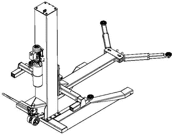
High-strength base for lifting machine
A lift, high-strength technology, applied in the direction of lifting frame, lifting device, lifting equipment safety device, etc., can solve the problems of fixed connection, poor safety, etc., to prolong service life, high safety, increase equipment stability Effect
- Summary
- Abstract
- Description
- Claims
- Application Information
AI Technical Summary
Problems solved by technology
Method used
Image
Examples
Embodiment 1
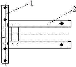
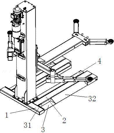
[0027] Such as image 3 As shown, the top of the support tube 2 is horizontally and vertically installed on the beam 1, and the outside of the support tube 2 is respectively provided with an outer reinforcement tube 3, and the outer reinforcement tube 3 is an L-shaped tube, and its top is connected to the beam 1. The junction is provided with a fastening strip 31, and the present invention effectively fixes the position of the outer reinforcement pipe 3 by adding the fastening strip 31, thereby improving the stability of the equipment, and because the reinforcement plate 32 is added on the outer reinforcement pipe 3, the outer reinforcement plate 32 are connected by triangular support pipe 2 to further improve the stability of the equipment;
[0028] The corresponding position inside the support tube 2 is provided with an inner reinforcing tube 4; the inner reinforcing tube 4 is a □-shaped hollow tube, and a fixing block 41 is arranged between the inner reinforcing tubes 4; by...
Embodiment 2
[0030] The surface layers of the beam 1, the support pipe 2, the outer reinforcement pipe 3, and the inner reinforcement pipe 4 are provided with a protective film; the present invention can effectively avoid the erosion of the base caused by air pollution and water in the external environment by adding a protective film, and effectively improve the Equipment safety, prolonging the service life by 25%, improving market competitiveness.
Embodiment 3
[0032] Described protective film, its preparation method comprises the following steps:
[0033]1. Use silicone-modified acrylic resin paint as the resin base material, add solid ceramic microbeads, alumina, kaolin, and glass frit in the same proportion as fillers, and add 4-benzoyloxy-2,2,6,6- Tetramethylpiperidine 0.1-0.2g / L, made into coating;
[0034] 2. Use an air spraying device to spray on the surface of beam 1, support tube 2, outer reinforcement tube 3, and inner reinforcement tube 4, and bake in a muffle furnace for 24 hours at a temperature of 650°C;
[0035] 3. A protective film is formed on the surface of the beam 1, the support pipe 2, the outer reinforcement pipe 3, and the inner reinforcement pipe 4.
[0036] The present invention adds a protective film on the surface of the beam 1, the support tube 2, the outer reinforcement tube 3, and the inner reinforcement tube 4, which can effectively prevent the reinforcement base from being in direct contact with corro...
PUM
 Abstract
Description
Claims
Application Information
 - R&D
- Intellectual Property
- Life Sciences
- Materials
- Tech Scout
- Unparalleled Data Quality
- Higher Quality Content
- 60% Fewer Hallucinations
Browse by: Latest US Patents, China's latest patents, Technical Efficacy Thesaurus, Application Domain, Technology Topic, Popular Technical Reports.
© 2025 PatSnap. All rights reserved.Legal|Privacy policy|Modern Slavery Act Transparency Statement|Sitemap|About US| Contact US: help@patsnap.com


