Method and device for determining exposure time of aerial photogrammetric camera in light-small unmanned aerial vehicle

A technology of aerial survey camera and exposure time, which is applied in the field of measuring the exposure time of aerial survey camera in light and small unmanned aerial vehicles. problem, to achieve the effect of improving accuracy and reducing dependence

Active Publication Date: 2015-07-08
CHINA TOPRS TECH
View PDF4 Cites 21 Cited by
  • Summary
  • Abstract
  • Description
  • Claims
  • Application Information

AI Technical Summary

Problems solved by technology

Patent No. CN201310012924.9 discloses a real-time acquisition and recording method of the exposure signal of a small aerial survey camera for unmanned aerial vehicles. The camera exposure signal is obtained from the front curtain of the camera shutter, and the time information of this signal is recorded by the GPS device as the camera exposure time, but in this method, the camera exposure signal is drawn from the front curtain position inside the camera and connected to the GPS device, so the structure is more complicated, and the camera shutter is susceptible to signal interference, resulting in shutter working errors, which further affects the accuracy of event recording accuracy, so this method still cannot well solve the technical problem of precise determination of the exposure moment of the aerial survey camera in the UAV

Method used


Image

  • Method and device for determining exposure time of aerial photogrammetric camera in light-small unmanned aerial vehicle
  • Method and device for determining exposure time of aerial photogrammetric camera in light-small unmanned aerial vehicle
  • Method and device for determining exposure time of aerial photogrammetric camera in light-small unmanned aerial vehicle

Examples


Embodiment Construction

[0033] The following will clearly and completely describe the technical solutions in the embodiments of the present invention with reference to the accompanying drawings in the embodiments of the present invention. Obviously, the described embodiments are only some, not all, embodiments of the present invention. The components of the embodiments of the invention generally described and illustrated in the figures herein may be arranged and designed in a variety of different configurations. Accordingly, the following detailed description of the embodiments of the invention provided in the accompanying drawings is not intended to limit the scope of the claimed invention, but merely represents selected embodiments of the invention. Based on the embodiments of the present invention, all other embodiments obtained by those skilled in the art without making creative efforts belong to the protection scope of the present invention.

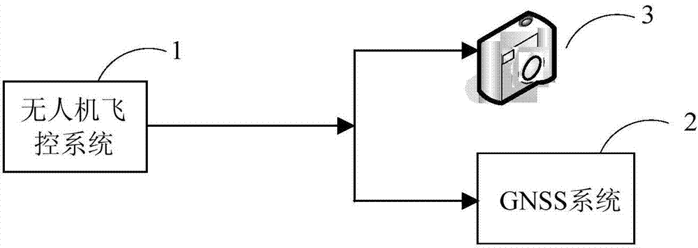
[0034] Such as figure 1Shown is a schematic structu...


PUM


Abstract

The invention relates to the field of aerial photogrammetry of unmanned aerial vehicles and particularly protects a method for determining the exposure time of an aerial photogrammetric camera in a light-small unmanned aerial vehicle. According to the method, a flight control system of the unmanned aerial vehicle generates an exposure test signal and an exposure control signal according to preset exposure control information; the aerial photogrammetric camera carries out an exposure action according to the exposure test signal and simultaneously generates a synchronous signal; the measuring system determines exposure delay time of the aerial photogrammetric camera according to the receiving time of the exposure test signal and the receiving time of the synchronous signal; a GNSS (Global Navigation Satellite System) determines accurate exposure time of the aerial photogrammetric camera according to the exposure delay time and the receiving time of the exposure control signal. The method has the advantages that the exposure time of the aerial photogrammetric camera can be accurately determined, no control or few control points can be realized, the accuracy of exterior orientation elements of interpolation-calculation aerial photogrammetric photographs is greatly improved, simultaneous exposure of a plurality of cameras is realized, and the size and the power consumption of the GNSS are reduced.

Description

technical field [0001] The invention relates to the field of unmanned aerial photogrammetry, in particular to a method and device for measuring the exposure time of an aerial survey camera in a light and small unmanned aerial vehicle. Background technique [0002] In the prior art, the precise time information of the exposure time of the digital camera in the UAV aerial photogrammetry work is not recorded or the time of the exposure pulse signal sent by the UAV flight control system is used as the camera exposure time, and the camera exposure delay is not considered. Therefore, it cannot accurately reflect the camera exposure moment. Without accurate time information, it is impossible to effectively match and correlate with precise coordinate information, which makes aerial photogrammetry require a large number of ground image control points for precision support. For example, the frequency of GPS (Global Positioning System, Global Positioning System) is generally It is abo...

Claims


Application Information

Patent Timeline
Patent Type & Authority Applications(China)
IPC IPC(8): G01C11/00
CPCG01C11/00G01C25/00
Inventor 李英成刘飞丁晓波刘沛罗祥勇任亚锋
Owner CHINA TOPRS TECH
Why Eureka
Try Eureka