
Cylindrical case and method for manufacturing cylindrical case

A cylindrical, shell technology, applied in chemical instruments and methods, machines/engines, high-efficiency propulsion technology, etc., can solve problems such as gap generation, and achieve the effect of high structural strength

Active Publication Date: 2015-07-08
IHI CORP +1
View PDF7 Cites 0 Cited by
  • Summary
  • Abstract
  • Description
  • Claims
  • Application Information

AI Technical Summary

Problems solved by technology

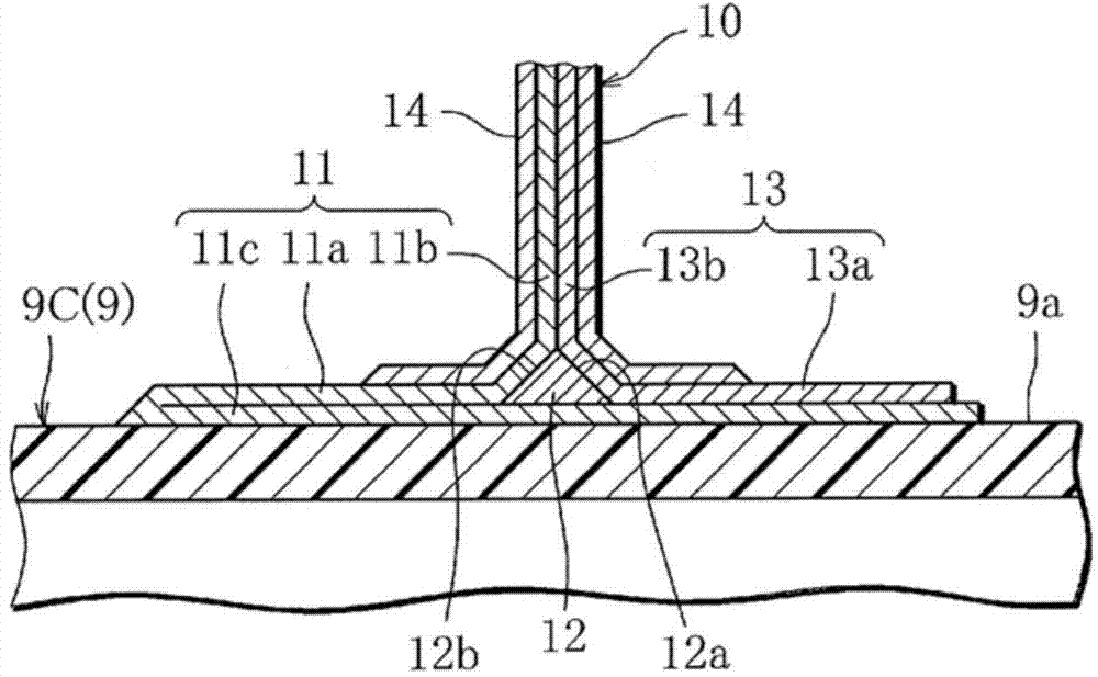
[0010] However, in the above-mentioned fan case, when the outward flange is formed on the outer peripheral surface of the case main body, in the state where the flange main body layer is arranged on the outer peripheral surface of the case main body in the circumferential direction, the flange main body layer The adhesion support layer is formed on both sides, so there is a problem that a gap may be generated between the base end portion of the flange main body layer and the adhesion support layer covering this portion, and solving this problem has become a conventional problem

Method used


Image

  • Cylindrical case and method for manufacturing cylindrical case
  • Cylindrical case and method for manufacturing cylindrical case
  • Cylindrical case and method for manufacturing cylindrical case

Examples


Embodiment Construction

[0032] Hereinafter, the present invention will be described based on the drawings.

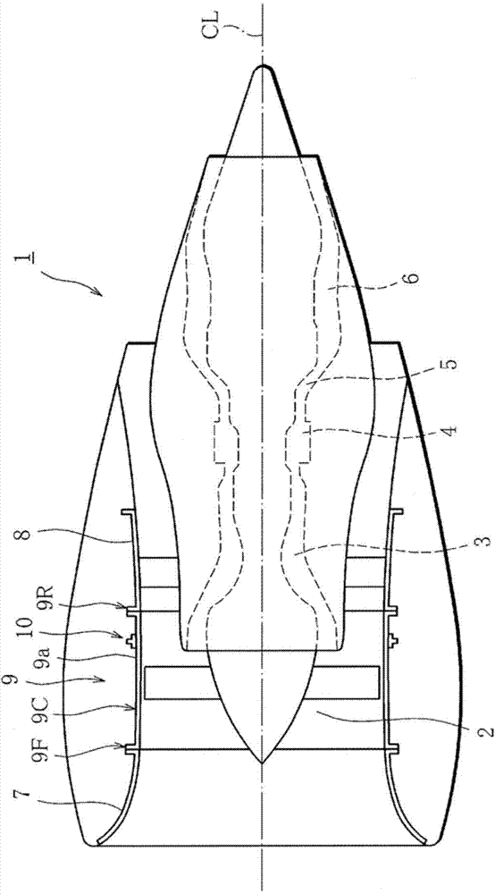
[0033] Figure 1 ~ Figure 4C One embodiment of the cylindrical casing of the present invention is shown, and in this embodiment, a case where the cylindrical casing of the present invention is a fan casing of a jet engine for an aircraft will be described as an example.

[0034] like figure 1 As shown, a jet engine 1 for an aircraft sends air taken in from the front (left in the figure) through a fan 2 having a plurality of fan blades to a compressor 3, injects fuel into the air compressed by the compressor 3 and burns Combustion is carried out in the chamber 4, and the high-pressure turbine 5 and the low-pressure turbine 6 are rotated by the expansion of the resulting high-temperature gas.

[0035] The fan case 9 covering the plurality of fan blades of the fan 2 has a cylindrical case main body 9C, and an outward flange 10 annularly arranged in the circumferential direction on the outer per...


PUM


Abstract

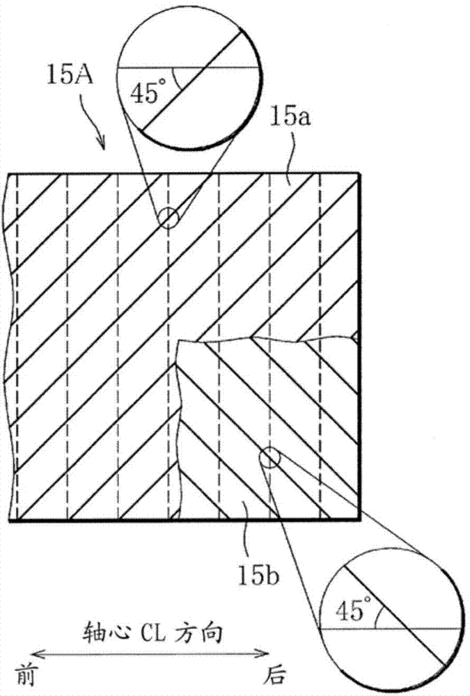
The present invention is provided with a case body (9C) comprising a composite material in which reinforcing fibers are impregnated with a thermosetting resin, and an outward-facing flange (10) on the case body (9C), the outward-facing flange (10) is provided with a bonded bonding layer (11c), a foundation layer (12) disposed on the bonding layer (11c), a one-side flange constituent layer (13) having a base layer (13a) layered on the bonding layer (11c) from a one-side inclined face (12a) of the foundation layer (12) and a wall layer (13b) standing upright from the one-side inclined face (12a), and an other-side flange constituent layer (11) having the base layer (13a) layered on the bonding layer (11c) from an other-side inclined face (12b) of the foundation layer (12) and a wall layer (11b) standing upright from the other-side inclined face (12b), the foundation layer (12) is formed by layering a roving layer, and the flange constituent layers (11, 13) are formed by layering a plurality of biaxial fabric layers including a biaxial fabric (15) having a non-crimped structure. High structural strength can thereby be maintained in an outward-facing flange of a fan case made from a composite material of reinforcing fibers and a thermosetting resin.

Description

technical field [0001] The present invention relates to, for example, a cylindrical casing used as a fan casing covering fan blades of a jet engine for an aircraft, and a method of manufacturing the cylindrical casing. Background technique [0002] For example, the above-mentioned fan case covering the fan blades of a jet engine for an aircraft requires light weight and high strength. In order to meet these requirements, a composite material of reinforced fiber and thermosetting resin has been tried as a material for the fan case. [0003] In the above-mentioned fan casing, in the middle part of the cylindrical casing main body that covers the fan blades, for example, a structure such as a gear box is installed, or a structure for connecting the jet engine to the wing or the like is formed according to the design. The outward flange for transmitting the thrust of the jet engine to a part of the structure of the airframe is arranged in a ring shape along the circumferential d...

Claims


Application Information

Patent Timeline
Patent Type & Authority Applications(China)
IPC IPC(8): B29C70/06B29C70/10F01D25/24F02C7/00B29K105/08B29L31/30
CPCY02T50/672F01D21/045F01D25/24B29C70/222F02K3/06B29L2031/7504B29C70/446F05D2300/603Y02T50/60Y10T156/1051B29C70/06F02C7/00B29C70/10B32B37/10B32B37/18B32B38/0012B32B38/08B32B2305/08B32B2305/18F01D25/005F01D25/243F05D2220/40F05D2300/44F05D2300/611F05D2300/614
Inventor 村上务奥村郁夫重成有原田敬段佑辅
Owner IHI CORP
Learn More