

Surface cleaning equipment
A surface cleaning and equipment technology, applied in the direction of carpet cleaning machines, machine parts, etc., can solve problems such as inconvenient use, and achieve the effects of convenient use, reduced water content, and good suction effect
- Summary
- Abstract
- Description
- Claims
- Application Information
AI Technical Summary
Problems solved by technology
Method used
Image

Examples
Embodiment 1
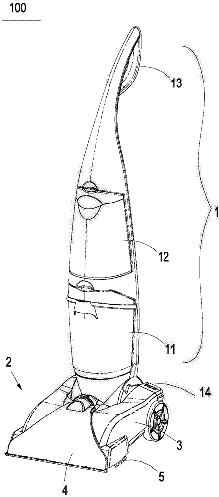
[0038] like figure 1 The surface cleaning equipment is shown in 100, which is used to clean the rug cleaning machine such as cleaning the carpet. The upper part of the handle is 1 and the bottom 2 is below.The handle 1 is equipped with a suction mechanism 11 composed of pumping sources, dirty solution recovery boxes, and mouth suction. The cleaning liquid supply mechanism, handle 13 and other components composed of water tank 12, pump, conveyor pipeline, etc.The base 2 is used to suck the dirt on the carpet and send it into the dirt collection unit of the handle 1 when the carpet is moving on the carpet.The base 2 has a shell 3, the shell 3 extends on the left and right directions, the mouth suction 4 is set on the front side of the shell 3, and the mouth 4 is a flat -shaped mouth that extends about one and one extension.4 The back side of the brush component 5, the brush component 5 is set near the water spraying port to the water spraying water to clean the carpet (not shown in ...
Embodiment 2
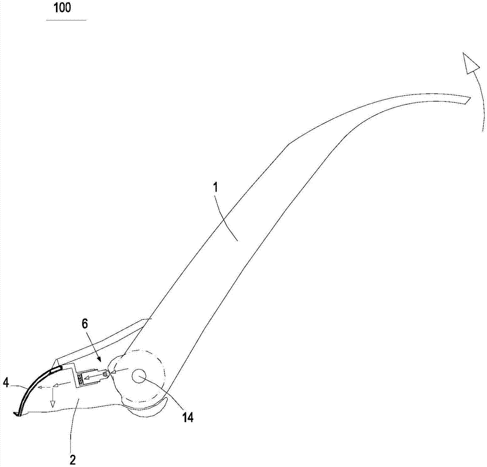
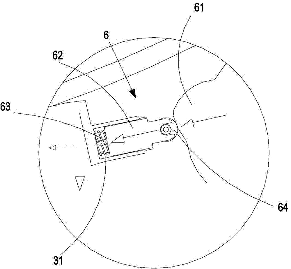
[0042] like Figure 4 It shows that the picture is the surface cleaning equipment 100 'with a tight mechanism 6' with another structure. The difference between the pressure mechanism 6 in the pressure mechanism 6 in the above -mentioned Example 1 is: up, down and downThe specific structure of the tightness is the opposite. As shown in the figure, the upper pressure tightness is 61 ', the lower part of the lower pressure is 62', the spring 63 'and the storage slot 15' are also set in the handle1 The front side of the lower part.The rolling wheel 64 'is installed on the lower end of the push rod 61', and the spring 63 'is set between the upper part of the push rod 61' and the storage slot 15 '.Its work process is similar to the above -mentioned pressure mechanism 6, so I won't go into details here.
Embodiment 3
[0044] like Figure 5 It is shown that the attached picture is the surface cleaning equipment 101 of the tight mechanism 7 with another structure. In the tightness mechanism 7, the upper pressure is one camwheel 71, the lower pressure tightness is one pressure block 72 72EssenceThe upper end of the pressure block 72 is fixed with elastic ring 73 made of rubber.When the handle 74 is tilted backwards compared to the base 75, the camworm surface 71 faces the forward and downward elastic ring 73, the elastic ring 73 generates elastic deformation, the suction mouth 77 in the front of the shell 76 will be forced to clean the ground with the ground to clean the groundfit.
PUM
 Abstract
Description
Claims
Application Information