
Automatic head and tail residue monitoring method of hot rolling strip steel

An automatic monitoring and hot-rolled strip technology, applied in the direction of tail-end control, etc., can solve the problems of inadvertent observation, unclear observation, missed detection or misjudgment, etc., to reduce the risk of scrap steel and accident expansion , Improve production stability, avoid missed detection and misjudgment

Active Publication Date: 2015-07-15
BAOSHAN IRON & STEEL CO LTD
View PDF9 Cites 13 Cited by
  • Summary
  • Abstract
  • Description
  • Claims
  • Application Information

AI Technical Summary

Problems solved by technology

[0007] 1. Heavy workload: Operators are required to carefully monitor each movement of the flying shears;
[0008] 2. Poor reliability: because the operator observes the CRT terminal with the naked eye, it is affected by objective factors such as the site environment, the size of the tongue or fish tail, and the drop angle, or due to the operator's fatigue, lack of concentration, and inattentive observation Due to subjective reasons, it is very easy to fail to observe or observe clearly, resulting in missed detection or misjudgment;
[0009] 3. Long reaction time: The reaction time from the operator discovering the phenomenon of leading and tailing to taking measures to stop the steel feeding may be relatively long, that is, if the intervention is not timely, the consequences may cause the tongue or fish tail to be brought into the finishing mill and cause Scrap rolling; it is also possible that the tongue or fish tail is brought between the vertical roll and the first rolling mill. Due to the narrow space in this area, the crane cannot lift it, and it often takes a long time to process it, resulting in the expansion of the accident.

Method used


Image

  • Automatic head and tail residue monitoring method of hot rolling strip steel
  • Automatic head and tail residue monitoring method of hot rolling strip steel
  • Automatic head and tail residue monitoring method of hot rolling strip steel

Examples


Embodiment Construction

[0043] The method for automatic monitoring of the hot-rolled strip head and tail of the present invention will be further described in detail below in conjunction with the accompanying drawings and specific embodiments.

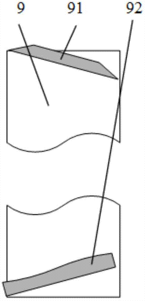
[0044] image 3 A schematic diagram of the leading and tailing phenomena. After the head of strip steel 9 is cut by flying shears 4, tongue 91 is not completely separated from strip steel 9, but rides on strip steel 9, enters descaling box 5 with the form of folding. Similarly, after the tail of the strip steel 9 is cut by the flying shears 4, the fish tail 92 is not completely separated from the strip steel 9, and enters the descaling box 5 in a folded form.

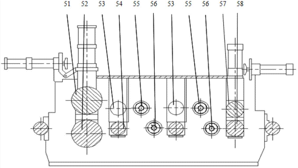
[0045] figure 2 It is a structural schematic diagram of phosphorus removal box 5. The phosphorus removal box 5 includes an upper pinch roller 51 at the entrance, a lower pinch roller 52 at the entrance, a water collector 53, a roller table 54 for the phosphorus removal box, an upper water header 55...


PUM


Abstract

The invention discloses an automatic head and tail residue monitoring method of a hot rolling strip steel. The method comprises the following steps: S11, a function of measuring the roll gaps and the rotating speeds of an inlet pinch roll and an outlet pinch roll of a dephosphorization box in real time is started; S12, whether the roll gap and the rotating speed of the inlet pinch roll meet a first warning condition is judged, if so, a step S14 is executed, and if not, a step S13 is executed; S13, whether the roll gap and the rotating speed of the outlet pinch roll meet a second warning condition is judged, if so, a step S14 is executed, and if not, a step S12 is executed; and S14, warning information is output, and steel feeding is stopped. The method has the advantages that while the labor intensity of an operation worker is reduced, the monitoring reliability is improved, the risk of producing steel scrap is reduced, the accident extensification is prevented, and the stability of hot rolling strip steel production is improved.

Description

technical field [0001] The invention relates to an automatic monitoring method in the process of hot-rolling strip steel, in particular to a method for automatically monitoring the strip head and tail phenomenon after the fly-shear head cuts the tail. Background technique [0002] The technological process of hot-rolled strip includes heating, rough rolling, finishing rolling, coiling and other processes. figure 1 It is a schematic diagram of a hot-rolled steel strip production line in the prior art. According to the rolling plan, the slab is loaded into the walking heating furnace 1. After the slab is heated to the target temperature specified by the process, it is transported to the rough rolling unit 2 . After the rough rolling unit 2 rolls the slab with a thickness of 200-250 mm into an intermediate billet with a thickness of 38-60 mm, it enters the finish rolling unit through the measurement of the optimized shearing system 3 . Cut the head and tail through the four-...

Claims


Application Information

Patent Timeline
IPC IPC(8): B21B37/72
CPCB21B37/72
Inventor 张志超幸利军陈炎敏张先念孙彤彤
Owner BAOSHAN IRON & STEEL CO LTD
Learn More