Sand core structure and manufacturing method for sand core

A technology of sand core and core head, applied in the field of sand core structure and sand core production, can solve the problems of sand core sand cannot be filled, casting sticky sand cannot be cleared, casting size deviation, etc., to achieve simple structure and ensure casting Quality, accurate positioning effect

Inactive Publication Date: 2015-07-15
桐乡合德机械有限公司
View PDF5 Cites 6 Cited by
  • Summary
  • Abstract
  • Description
  • Claims
  • Application Information

AI Technical Summary

Problems solved by technology

However, since the bottom of the existing core head is a sand-scraping surface, when the sand-scraping surface is uneven, the bottom surface of the core head corresponding to the sand-scraping surface will be offset against the bottom surface of the corresponding core head positioning groove, thereby causing the sand core to be deflected, resulting in Deviation in casting size
In order to avoid the above-mentioned problems, in the prior art, the bottom of the core head is changed to a non-scraping surface by changing the sand filling port of the core box, but this structure has certain limitations in actual operation, that is, the sand Influenced by the core structure, if the position of the sand filling is changed, the sand at the corners of the sand core cannot be filled easily, which will cause the sand sticking to the casting and cannot be cleared, which will seriously affect the quality of the casting

Method used


Image

  • Sand core structure and manufacturing method for sand core
  • Sand core structure and manufacturing method for sand core

Examples


Embodiment

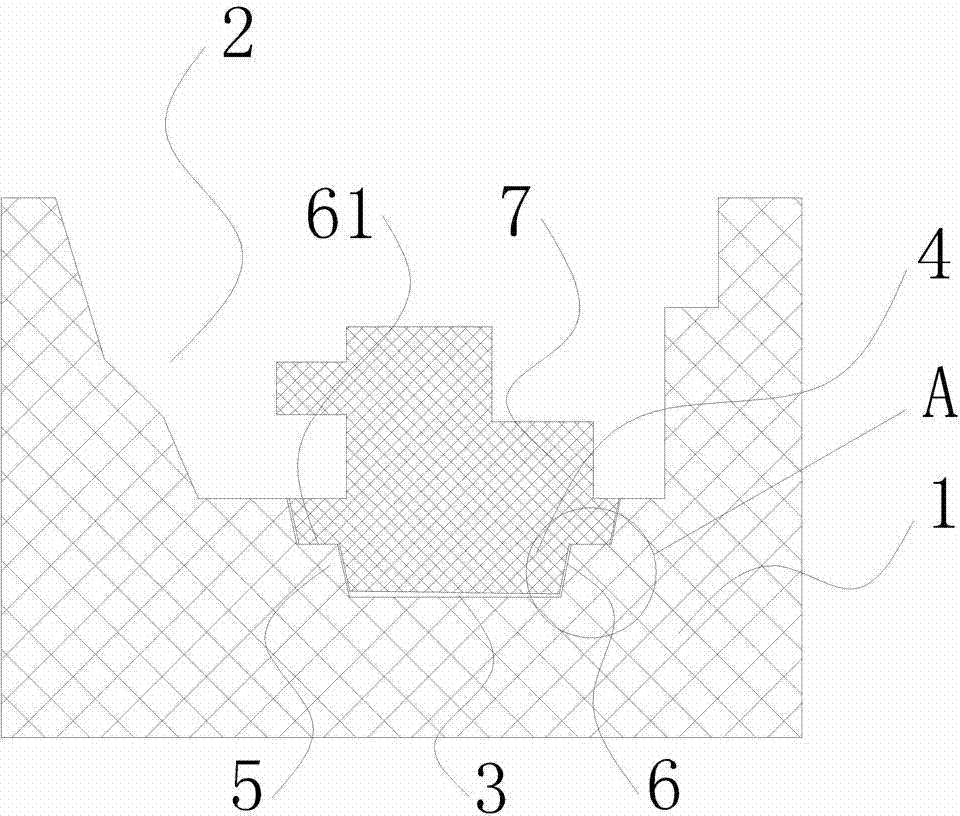
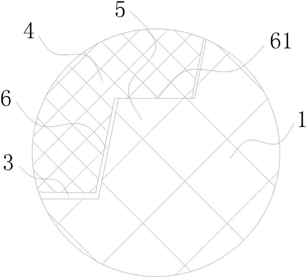
[0021] Such as figure 1 As shown, a sand core structure of the present invention includes a core base 1, a cavity 2 with an opening facing upward is provided on the core base 1, and a circular core head positioning groove 3 is opened at the bottom of the cavity 2, The sand core 7 is inserted in the core head positioning groove 3, and the sand core 7 is inserted in the core head positioning groove 3 through the core head 4 extending at the bottom end of the core head positioning groove 3. Extend horizontally on the wall to form an annular support boss 5, and the annular support boss 5 is coaxial with the core head positioning groove 3, such as figure 2 As shown, the core head 4 corresponding to the annular support boss 5 extends horizontally inward to form an interfitting annular notch 6, the bottom of the annular notch 6 is connected to the bottom surface of the core head 4, and the horizontal direction is connected to the outer ring surface. The core 7 is horizontally suppo...


PUM


Abstract

The invention relates to the foundry industry and discloses a sand core structure and a manufacturing method for a sand core. The sand core structure is simple and enables the core print of the sand core to be steadily and precisely positioned in a core print positioning tank, thereby guaranteeing the quality of a casting. The sand core structure and the manufacturing method for the sand core overcome the technical problems of dimensional deviation of a casting due to easy deflection of a sand core, severely impaired quality of the casting and the like when the bottom surface of the core print of the sand core is a sand strickling surface. The sand core structure comprises a core print seat; a cavity with an upward opening is arranged on the core print seat; the bottom of the cavity is provided with the core print positioning tank; the sand core is inserted into and connected with the core print positioning tank in a mating manner via the core print; an annular supporting boss horizontally extends on an internal wall surface close to the bottom of the core print positioning tank; a mating annular gap horizontally extends on the core print corresponding to the annular supporting boss; and the sand core is horizontally supported on the annular supporting boss through an upper annular surface corresponding to the annular gap.

Description

technical field [0001] The invention relates to the foundry industry, in particular to a core head which is installed stably and reliably so as to ensure the precise positioning of the sand core in the mold cavity of the core seat and ensure the quality of the casting and a sand core manufacturing method. Background technique [0002] In the foundry industry, the sand core (mud core) is fixed and positioned in the cavity by the core head, so it is necessary to ensure that the core head is installed smoothly and reliably, and the positioning accuracy is high. However, since the bottom of the existing core head is a sand-scraping surface, when the sand-scraping surface is uneven, the bottom surface of the core head corresponding to the sand-scraping surface will be offset against the bottom surface of the corresponding core head positioning groove, thereby causing the sand core to be deflected, resulting in Deviations in casting dimensions. In order to avoid the above-mention...

Claims


Application Information

Patent Timeline
IPC IPC(8): B22C9/10
CPCB22C9/10
Inventor 孙袁徐英珠
Owner 桐乡合德机械有限公司
Why Eureka
Try Eureka