Special vibrating screen for sulfur-contained oil and gas field

A vibrating screen and oil and gas field technology, which is applied in wellbore/well components, earthwork drilling, construction, etc., can solve the problems of human safety and inapplicability that are easy to endanger the operator, and achieve the goal of reducing poisoning incidents, improving efficiency, and stabilizing nitrogen gas Effect

Inactive Publication Date: 2015-07-15
SICHUAN XILIN OIL SUPPLIES EQUIP
View PDF0 Cites 0 Cited by
  • Summary
  • Abstract
  • Description
  • Claims
  • Application Information

AI Technical Summary

Problems solved by technology

[0005] The purpose of the present invention is to solve the problem that the petroleum drilling fluid screening equipment in the prior art is not suitable for oil fields with high sulfur content, which is easy to endanger the artificial safety of operators, and to provide a special vibrating screen for sulfur-containing oil and gas fields with safe operation and low price

Method used


Image

  • Special vibrating screen for sulfur-contained oil and gas field
  • Special vibrating screen for sulfur-contained oil and gas field

Examples


Embodiment 1

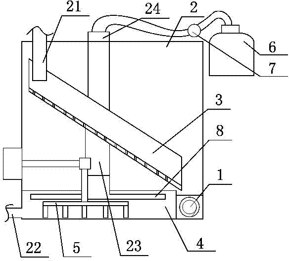
[0027] A special vibrating screen for sulfur-containing oil and gas fields, such as figure 1 , figure 2 As shown, it includes a closed box 2 with a feed port 21, a discharge port 22, an air return pipe 23 and an air outlet pipe 24;

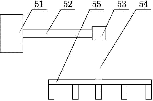
[0028] Described airtight box 2 inside is equipped with the vibrating screening net 3 that tilts to set, collection pool 4, agitator 5 and spiral chip conveyor 1; 51 connection, the other end extends into the main connecting rod 52 in the airtight box 2, the steering gear 53 installed on the other end of the main connecting rod 52, and the stirring rod 55 connected to the steering gear 53 through the secondary connecting rod 54;

[0029] The collection pool 4 is located directly below the vibrating screening net 3, the stirring rod 55 is located in the collecting pool 4, and the spiral chip conveyor 1 is installed directly below the lowest end side of the vibrating screening net 3; Right above the side of the highest end of the screen 3 , the d...

Embodiment 2

[0035] In this embodiment, on the basis of Embodiment 1, a one-way valve 7 and a gas storage tank 6 are added, and the specific setting method is as follows:

[0036] The air return pipe 23 is provided with a one-way valve 7 . One end of the one-way valve 7 communicates with the gas return pipe 23, and the other end of the one-way valve 7 communicates with the gas storage tank 6, and the gas stored in the gas storage tank 6 in this embodiment is nitrogen.

[0037] In the present invention, nitrogen gas is used to fill the recovered slurry, and then the hydrogen sulfide gas in the recovered slurry is discharged, and then when the gas flowing out of the step (3) of Example 1 is discharged into the atmosphere after removing the hydrogen sulfide gas, it can effectively prevent Air pollution and effective cost savings.

Embodiment 3

[0039] The only difference between this embodiment and Embodiment 1 or 2 is that one end of the air return pipe 23 extending into the collection tank 4 is also provided with a distributing device 8, which is disc-shaped and has a Air inlet and more than two air distribution holes. In this embodiment, there are 10 gas distribution holes, which are evenly distributed on the disk-shaped gas distribution device 8 .

[0040] Through the arrangement of the gas distributing device, the gas charged into the recovered slurry is effectively evenly dispersed in it, thereby improving the precipitation efficiency of hydrogen sulfide gas.

[0041] In order to compare the desulfurization effect of the present invention, the present invention provides a control group, and its specific operation steps are as follows: on the basis of Example 1, the step of stirring the recovered slurry in the collection tank by the stirring device is removed, and simultaneously No inert gas is introduced.


PUM


Abstract

The invention discloses a special vibrating screen for a sulfur-contained oil and gas field. The vibrating screen comprises a closed box which has a feed port, a discharge port, a gas return pipe and a gas outlet pipe, wherein an inclined vibrating screen subnet, a collecting pool, a stirring device and a spiral chip remover are mounted in the closed box; the stirring device consists of a motor, a main connecting rod, a steering gear and a stirring rod; the motor is mounted outside the closed box; one end of the main connecting rod is connected with the motor, and the other end extends into the closed box; the steering gear is mounted at the other end of the main connecting rod; the stirring rod is connected to the steering gear through a secondary connecting rod; the collecting pool is positioned rightly below the vibrating screen subnet; the stirring rod is positioned in the collecting pool; the spiral chip remover is mounted rightly below one side of the lowermost end of the vibrating screen subnet; the feed port is positioned rightly above one side of the topmost end of the vibrating screen subnet; the discharge port is positioned at the bottom end of the collecting pool; the gas outlet pipe is positioned at the top end of the closed box; and the gas return pipe is positioned at the top end of the closed box, and extends into the collecting pool. The vibrating screen has such advantages as operation safety, environmental protection and good sulfur removing effect.

Description

technical field [0001] The invention relates to the technical field of petroleum drilling, in particular to a special vibrating screen for sulfur-containing oil and gas fields. Background technique [0002] Oil drilling mud shaker is an important equipment to reduce the solid phase content in drilling fluid. Drilling fluid circulating from the downhole to the surface must first pass through the shale shaker to remove solid particles with large diameters before entering the desander or desilter to further reduce the solid content. [0003] When drilling in high-sulfur oil and gas fields, the drilling fluid circulated to the surface contains more hydrogen sulfide. After the drilling fluid reaches the ground, hydrogen sulfide is separated from the drilling fluid, threatening the personal safety of drilling engineers and technicians. The safe and efficient exploration and development of high-sulfur oil and gas fields in drilling fluids is one of the technical problems faced by...

Claims


Application Information

Patent Timeline
Patent Type & Authority Applications(China)
IPC IPC(8): E21B21/01E21B21/06
CPCE21B21/065
Inventor 贺昶明
Owner SICHUAN XILIN OIL SUPPLIES EQUIP
Why Eureka
Try Eureka