
Pumped storage thermodynamic system of thermal power plant

A technology of pumped storage and thermal systems, applied in steam engine devices, machines/engines, mechanical equipment, etc., can solve throttling loss, large thermal shock of thermal system, system operating efficiency, operating stability, economy, and safety Impact and other issues

Active Publication Date: 2015-07-15
CHINA POWER ENG CONSULTING GRP CORP EAST CHINA ELECTRIC POWER DESIGN INST
View PDF6 Cites 2 Cited by
  • Summary
  • Abstract
  • Description
  • Claims
  • Application Information

AI Technical Summary

Problems solved by technology

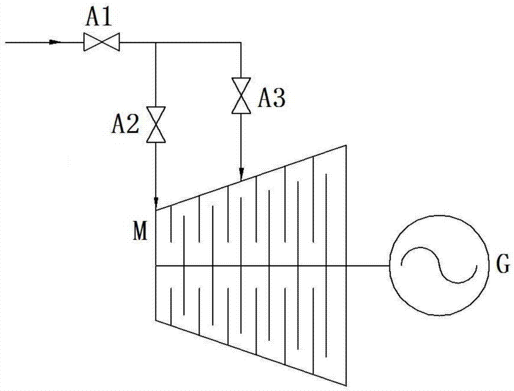
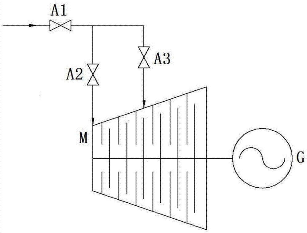
[0011] All in all, the main shortcomings of the existing primary frequency modulation technology are as follows: 1) There is a throttling loss in order to achieve the purpose of frequency modulation; 2) There is a large thermal shock to the thermal system during the frequency modulation process
These shortcomings will have a negative impact on system operating efficiency, operational stability, economy, and security.

Method used


Image

  • Pumped storage thermodynamic system of thermal power plant
  • Pumped storage thermodynamic system of thermal power plant
  • Pumped storage thermodynamic system of thermal power plant

Examples


Embodiment 1

[0124] Embodiment 1 The pumped storage thermal system of the local feedwater heater draining water

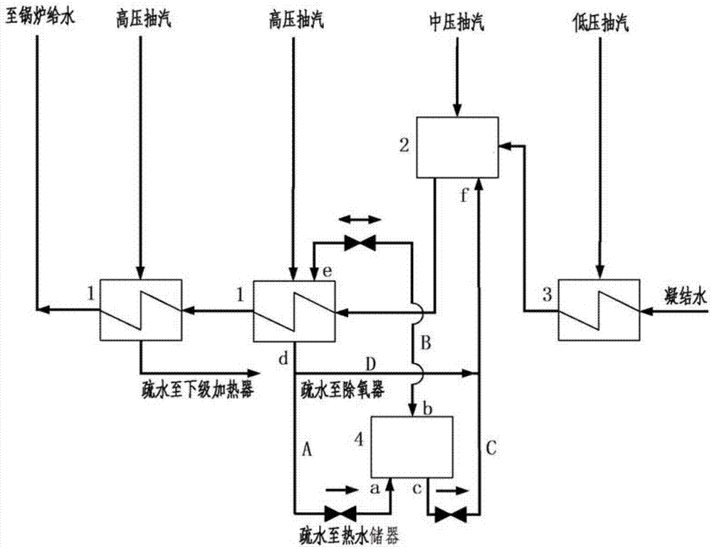
[0125] image 3 Shows the pumped storage thermal system flow of the local heater drain, as follows: When the frequency of the power grid is too high and the output of the unit needs to be reduced, part of the drain of the primary feedwater heater (3# high addition) is arranged according to the existing thermal system It is discharged into the deaerator, and the other part of the water enters the newly configured hot water reservoir, through which the heat of a part of the water in the original thermal system is collected and stored. At this time, the flow rate of hydrophobic water entering the deaerator from 3# is reduced. In order to ensure the constant main steam flow rate, the condensed water volume needs to be increased, and the corresponding steam volume required by the condensed water heater and deaerator to heat the condensed water increases. As a result, the amount of ...

Embodiment 2

[0129] Example 2 Pumped-storage thermodynamic system for water-draining of feedwater heaters adjacent to the machine

[0130] Figure 4 Showing the pumped storage thermodynamic system for water drainage of adjacent machine heaters: part of the water is drawn from the adjacent unit’s supercharger to the hot water storage, and when the frequency of the grid is too low, the hot water is transferred to The water in the reservoir is drained into the deaerator of the machine to increase the heat source of the deaerator, thereby reducing the inlet medium-pressure steam extraction flow, allowing more steam to enter the low-pressure cylinder to do work, increasing the output of the unit, and increasing the grid frequency.

[0131] result

[0132] According to calculations, using the pumped storage thermal system of Example 2, if the heat of the low-parameter adjacent unit is transferred to the system of the high-parameter unit, the utilization rate of the heat in the high-parameter hi...


PUM


Abstract

The invention relates to a pumped storage thermodynamic system of a thermal power plant. Specifically, the pumped storage thermodynamic system comprises a water feeding heater, a deoxidizing heater, a condensed water heater and a hot water storage device. The hot water storage device is arranged in the thermodynamic system, so that a part of drained water flowing out of a water system is stored in the hot water storage device, under the working condition that unit load needs adjusting, the drained water is supplemented to the thermodynamic system, and the effect of increasing the unit load or adjusting the frequency can be achieved. Throttling loss is avoided, impact on an original thermodynamic system is small, and the advantages in the aspects of operation economy and safety are remarkable.

Description

technical field [0001] The invention relates to the fields of power grid frequency regulation and thermal power generation, and in particular to a pumped storage thermal system of a thermal power plant. Background technique [0002] In order to ensure the safe and economical operation of the power grid, improve the control level of power quality and grid frequency, and quickly eliminate frequency fluctuations caused by grid load changes, the grid generally requires the steam turbine generator set to have the ability of primary frequency regulation, that is, the steam turbine is required The generator set has the ability to increase or decrease a certain amount of output in a short period of time to quickly respond to the drop or rise of the grid frequency. [0003] At present, the primary frequency modulation technology of thermal power turbine generator sets mainly includes: steam turbine main valve throttling frequency modulation, supplementary steam valve frequency modula...

Claims


Application Information

Patent Timeline
IPC IPC(8): F01K23/04
Inventor 申松林鲍金花施刚夜蒋健
Owner CHINA POWER ENG CONSULTING GRP CORP EAST CHINA ELECTRIC POWER DESIGN INST
Learn More