Multi-purpose LED lamp and its special installation structure
A technology of LED lamp and installation structure, which is applied in the direction of lighting devices, fixed lighting devices, lighting auxiliary devices, etc. It can solve the problems of affecting the service life of LED lamps, the inability of LED lamps to illuminate uniformly, and the complex structure of LED lamps to improve convenience. , Excellent convenience, and the effect of reducing production costs
- Summary
- Abstract
- Description
- Claims
- Application Information
AI Technical Summary
Problems solved by technology
Method used
Image
Examples
Embodiment 1
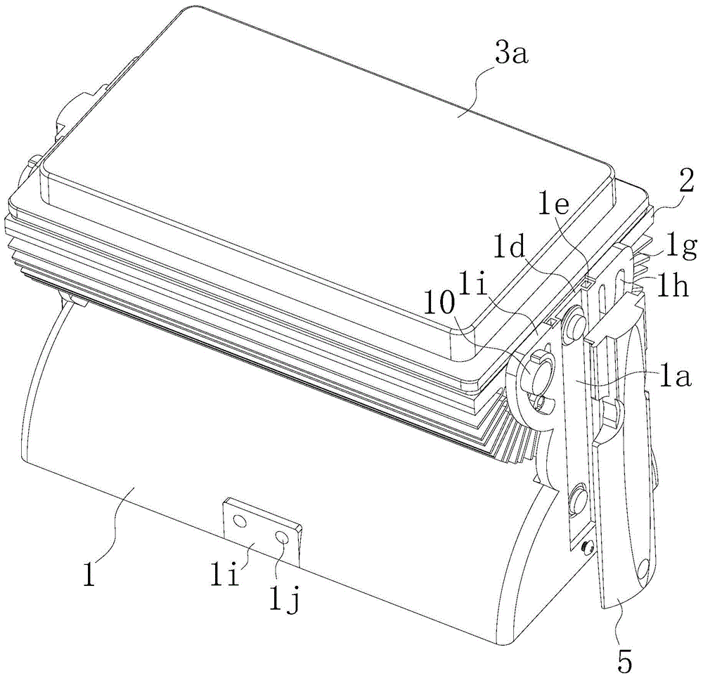
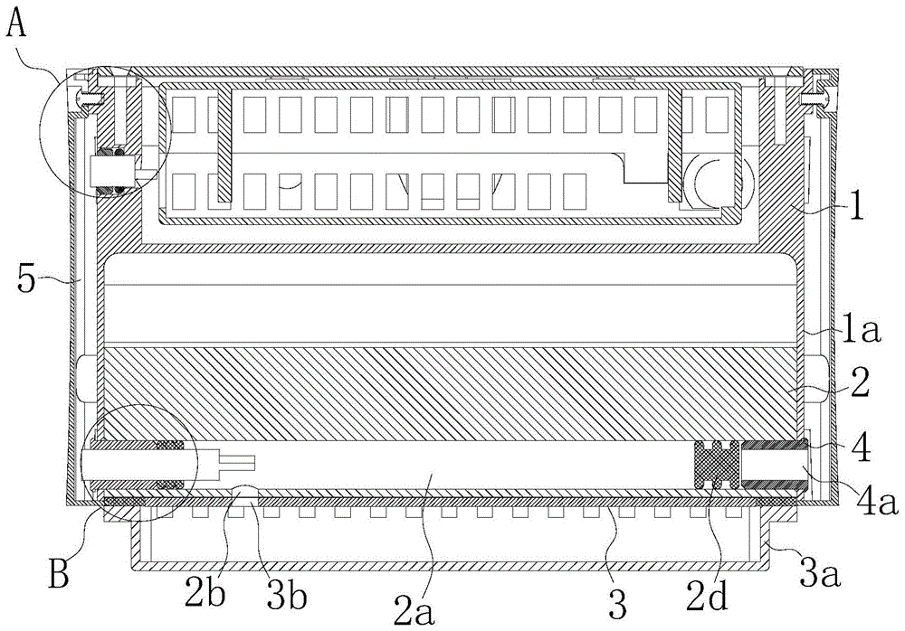
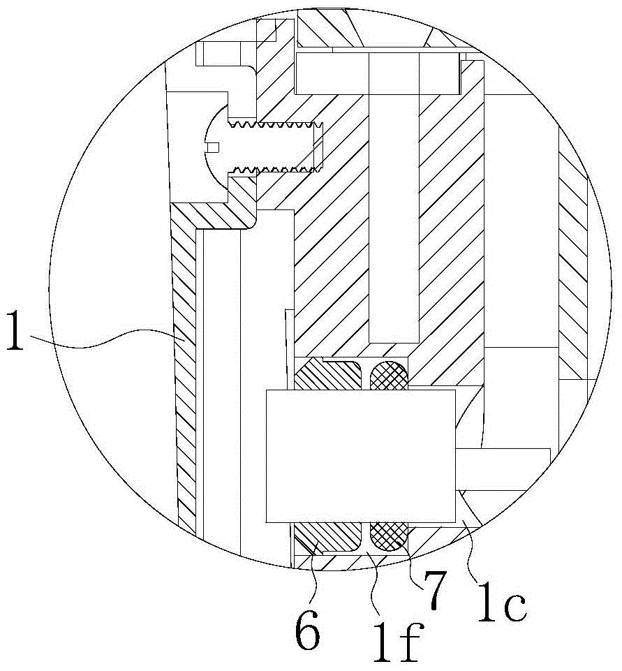
[0027] refer to Figure 1 to Figure 5 As shown, a multi-purpose LED lamp of the present invention includes a lamp holder 1, a power drive module is arranged inside the lamp holder 1, an aluminum alloy radiator 2 is hinged on the lamp holder 1, and the installation plane of the aluminum alloy radiator 2 An LED light board 3 is arranged on the top, and a lampshade 3a is arranged on the periphery of the LED lamp board 3. The lampshade 3a is preferably a light diffusion cover to prevent the light from being too dazzling and causing glare; the two ends of the lamp holder 1 along the length direction are provided with connecting plates 1a, an installation through hole 2a is provided along the length direction on the aluminum alloy radiator 2, and a connection hole 1b corresponding to the installation through hole 2a is provided on the connection plate 1a, and the two ends of the installation through hole 2a are connected to the corresponding connection hole 1b is connected in series...
Embodiment 2
[0033] refer to Image 6 As shown, a special installation structure for the above-mentioned multi-purpose LED lamp of the present invention includes installation platforms 1g arranged on both sides of the lamp holder 1 along the length direction, and is characterized in that two installation platforms 1g are provided with The inner screw hole 1h, the inner screw hole 1h is connected with a first L-shaped connecting piece 8 by screws, and the first L-shaped connecting piece 8 is composed of an integrally formed horizontal connecting plate 8a and a vertical connecting plate 8b. 8a and the vertical connecting plate 8b are provided with a first connecting hole 8c corresponding to the inner screw hole 1h, and the first L-shaped connector 8 is threaded and fixed through the first connecting hole 8c and the inner screw hole 1h by screws; Positioning through holes 8d are respectively provided at the proximal ends of the two ends of the horizontal connecting plate 8a along the length d...
Embodiment 3
[0036] refer to Figure 7 As shown, a special installation structure for the multi-purpose LED lamp of the present invention is basically the same as that of Embodiment 1, the difference is that there is no magnet 9 in this embodiment, but a vertical connecting plate 8b A second connection hole 8e is provided near one end of the horizontal connection plate 8a. A second L-shaped connecting piece 10 is connected to the second connecting hole 8e; one of the plates of the second L-shaped connecting piece 10 is provided with a third connecting hole 10a adapted to the second connecting hole 8e, and the other A fourth connecting hole 10b is provided on the board surface, and the second L-shaped connecting piece 10 is fixedly connected to the surface to be installed through the fourth connecting hole 10b by screws.
[0037] This installation method is mainly used when there is no magnet in the installation location. It has the same regulating effect as Example 2.
[0038] In additi...
PUM
 Abstract
Description
Claims
Application Information
 - R&D
- Intellectual Property
- Life Sciences
- Materials
- Tech Scout
- Unparalleled Data Quality
- Higher Quality Content
- 60% Fewer Hallucinations
Browse by: Latest US Patents, China's latest patents, Technical Efficacy Thesaurus, Application Domain, Technology Topic, Popular Technical Reports.
© 2025 PatSnap. All rights reserved.Legal|Privacy policy|Modern Slavery Act Transparency Statement|Sitemap|About US| Contact US: help@patsnap.com


