Energy isolation system of oil field united station and energy isolation method

An isolation system and combined station technology, applied in the field of electromechanical device safety equipment, can solve the problems of frequent production accidents, accidental release of energy, safety accidents, etc., and achieve the effects of avoiding equipment damage, controlling accidental release, and controlling risks.

Inactive Publication Date: 2015-07-15
盘锦金汇工程机械有限公司
View PDF8 Cites 2 Cited by
  • Summary
  • Abstract
  • Description
  • Claims
  • Application Information

AI Technical Summary

Problems solved by technology

[0003] For example, a typical oil field joint station includes buildings, oil storage tanks, sewage tanks, clean water tanks, pump rooms, power distribution rooms, process pipe networks and other devices. When the staff of the oil field joint station perform maintenance and other tasks, There are risks of accidents caused by the release of energy such as electricity, mechanical shock, chemical poisoning, and explosive liquids, and such risks are usually due to the accidental release of energy due to the misoperation of the staff, which in turn leads to safety accidents
[0004] In the prior art, there is no systematic and effective solution for accidents caused by the accidental release of energy in a typical oilfield combined station. The usual solution is usually as disclosed on pages 106-107 of the journal "Modern Occupational Safety" in the 8th issue of 2010 , The staff simply locks and tags out the energy isolation, but

Method used


Image

  • Energy isolation system of oil field united station and energy isolation method
  • Energy isolation system of oil field united station and energy isolation method
  • Energy isolation system of oil field united station and energy isolation method

Examples


Example Embodiment

[0029] Example 1

[0030] The main purpose of this embodiment is to provide an energy isolation system suitable for the oilfield field, during installation, maintenance, service and repair activities, to protect workers from accidental release of dangerous energy, and to prevent or reduce operation The energy isolation system and energy isolation method of the oilfield joint station that caused a safety accident by personnel misoperation.

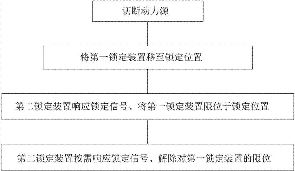
[0031] The energy isolation in this embodiment refers to the use of an energy isolation system to isolate and lock off the energy according to a certain procedure to ensure that relevant personnel working on equipment or devices are not injured.

[0032] Specifically, the energy isolation system of the oilfield joint station includes an energy isolation device and an electromechanical device to be isolated. The energy isolation device is provided with a first locking device, and the first locking device can move between the locked position and the...

Example Embodiment

[0049] Example 2

[0050] The main purpose of this embodiment is to provide an energy isolation system for the oilfield joint station that is suitable for the oilfield field and uses information technology to implement energy isolation, thereby effectively avoiding accidental release of dangerous energy, so as to prevent or reduce safety accidents caused by staff misoperation Energy isolation system and energy isolation method of oilfield joint station in China.

[0051] The difference between this embodiment and embodiment 1 is mainly the movement structure and the control structure for locking or unlocking the first locking device

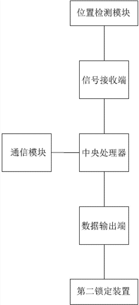
[0052] The energy isolation system of the oilfield joint station in this embodiment mainly further includes a central processing unit. The second locking device is controlled by the central processing unit. The central processing unit is connected to a position detection module for detecting that the first locking device is in the locked position or the...

Example Embodiment

[0064] Example 3

[0065] The difference between this embodiment and the first embodiment is mainly the unlocking structure and unlocking method of the second locking device.

[0066] The main purpose of this embodiment is also to provide an energy isolation system for the oilfield joint station that is suitable for the oilfield field and uses information technology to implement energy isolation, thereby effectively avoiding accidental release of dangerous energy, and preventing or reducing safety accidents caused by operator misoperation The energy isolation system and the method for isolating energy of the oilfield joint station, further, provide a more flexible management method to avoid the failure to unlock the energy isolation system and energy isolation method of the oilfield joint station that affects the construction period due to the absence of the supervisor ,details as follows:

[0067] The central processing unit in this embodiment is provided with a communication modul...


PUM


Abstract

An energy isolation system of an oil field united station comprises an energy isolation device and a to-be-isolated electromechanical device, wherein a first locking device is arranged on the energy isolation device and can move between a locking position and an unlocking position, and the energy isolation device blocks or isolates energy released by the to-be-isolated electromechanical device when the first locking device is located in the locking position; at least one second locking device is also arranged on the energy isolation device and can keep the first locking device in the locking position. The at least one independent second locking device is additionally arranged outside the energy isolation device and limits the unlocking moving method of the first locking device to prevent the first locking device from moving into the unlocking position, the risk of accidental release of energy caused by misoperation can be effectively prevented, and the accidental release of hazardous energy can be effectively controlled.

Description

technical field [0001] The invention relates to the field of safety equipment for electromechanical devices in production sites in the petroleum field, in particular to an energy isolation system and an energy isolation method for an oil field joint station. Background technique [0002] During the operation of the equipment in the production site in the petroleum field, the staff are always facing the danger of injury caused by the accidental release of energy. The energy that may cause danger to the staff includes, but is not limited to the following: electrical energy, mechanical Shock, chemical toxic and harmful substances, explosion shock, etc. [0003] For example, a typical oil field joint station includes buildings, oil storage tanks, sewage tanks, clean water tanks, pump rooms, power distribution rooms, process pipe networks and other devices. When the staff of the oil field joint station perform maintenance and other tasks, There are risks of accidents caused by t...

Claims


Application Information

Patent Timeline
IPC IPC(8): G05B19/048
CPCG05B19/048
Inventor 靖欣锡王娇赵强
Owner 盘锦金汇工程机械有限公司
Why Eureka
Try Eureka