
Sky image cloud cluster movement velocity computing method based on phase correlation principle

A technology related to motion speed and phase, which is applied in the fields of image processing and photovoltaic power prediction, can solve the problems of poor calculation result accuracy, complex calculation process, and prediction result error, and achieve the effect of reducing time consumption and simple and direct calculation process

Inactive Publication Date: 2015-07-15
NORTH CHINA ELECTRIC POWER UNIV (BAODING) +1
View PDF3 Cites 10 Cited by
  • Summary
  • Abstract
  • Description
  • Claims
  • Application Information

AI Technical Summary

Problems solved by technology

[0005] At present, the calculation and prediction of cloud displacement mostly adopts the segmentation matching method, that is, the sky image is first divided into multiple regions, and then each region of two adjacent images is matched to obtain the cloud displacement between the two sky images After that, linear extrapolation is used to predict the position of the cloud cluster at the next moment. This calculation method has a complicated calculation process, and the accuracy of the calculation results is poor. There is a large error between the prediction results and the actual situation.

Method used


Image

  • Sky image cloud cluster movement velocity computing method based on phase correlation principle
  • Sky image cloud cluster movement velocity computing method based on phase correlation principle
  • Sky image cloud cluster movement velocity computing method based on phase correlation principle

Examples


Embodiment 1

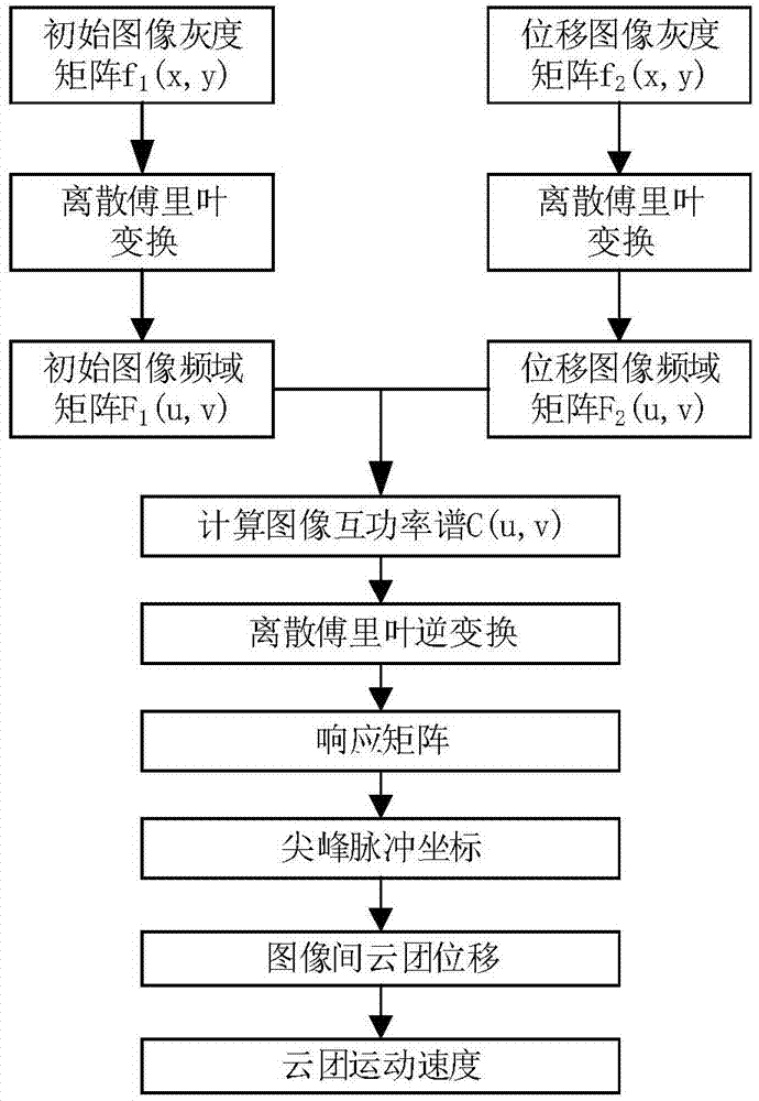
[0065] figure 1 It is a specific algorithm flow chart of the present invention. The process consists of the following steps:

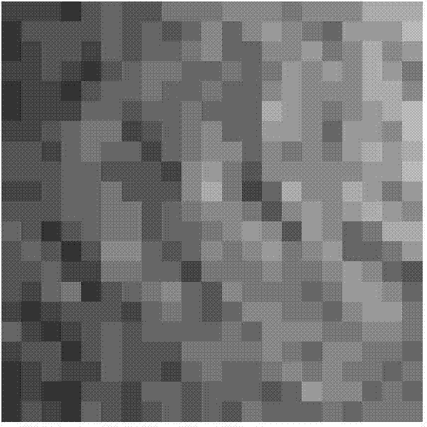
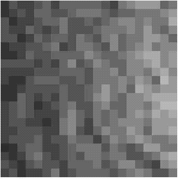
[0066] Step 1: Take t 1 The time is 9:55am, and t is obtained through ground-based observation equipment 1 The initial sky image at time (9:55am) ( figure 2 ), take Δt as 5 minutes, and obtain the current t after Δt time (5min) through the ground-based observation equipment 2 Time (10:00am) displacement sky image ( image 3 ). Its gray value matrix is ​​respectively:

[0067]

[0068]

[0069]

[0070] Step 2: Obtain the spectral matrix F of the initial image and the displaced image by two-dimensional discrete Fourier transform 1 (u,v), F 2 (u,v).

[0071] The two-dimensional discrete Fourier transform process is as follows. Suppose an image grayscale matrix is ​​f(x, y), its resolution is M×N, and its two-dimensional discrete Fourier transform formula is:

[0072] F ( ...

Embodiment 2

[0107] Step 1: Get the initial image at 2:59pm on a certain day ( Figure 4 ) and the current 3:00pm image ( Figure 5 ), generate both gray value matrix f 3 (x,y) and f 4 (x,y).

[0108] in

[0109]

[0110]

[0111]

[0112] Step 2: Obtain the spectral matrix F by two-dimensional discrete Fourier transform 3 (x,y), F 4 (x,y).

[0113] f 3 The real part of (x,y) is

[0114]

[0115] f 3 The imaginary part of (x,y) is

[0116]

[0117]

[0118] f 4 The real part of (x,y) is

[0119]

[0120] f 4 The imaginary part of (x,y) is

[0121]

[0122]

[0123] Step 3: Calculate the cross-power spectrum C(u,v) between the initial image and the displaced image.

[0124] The real part of C(u,v) is

[0125]

[0126] The imaginary part of C(u,v) is

[0127]

[0128] Step 4: Perform inverse Fourier transform on the image cross-power spectrum C(u,v) to obtain the response matrix F -1 {C(u,v)}, divide the response matrix into four parts on avera...


PUM


Abstract

The invention relates to a sky image cloud cluster movement velocity computing method based on the phase correlation principle. The method comprises the following steps that 1, an initial image and a displacement image of a sky image are acquired; 2, gray matrixes of the initial image and the displacement image are generated respectively; 3, image frequency spectrums of the initial image and the displacement image are acquired through the two-dimensional Fourier transform; 4, cross-power spectrum of the initial image and the displacement image and an inverse Fourier transform response matrix of the cross-power spectrum are computed; 5, spike pulse coordinates of the response matrix are extracted to serve as cloud cluster displacement vectors; 6, the cloud cluster movement velocity is computed according to the cloud cluster displacement and the image time interval. According to the sky image cloud cluster movement velocity computing method based on the phase correlation principle, the operation flow is simple and direct, and the cloud cluster displacement prediction consuming time can be greatly shortened; the overall movement condition of a cloud cluster in the image can be recognized more effectively, and due to normalization processing in cross-power spectrum computing, the higher robustness is achieved for global image noise.

Description

technical field [0001] The invention relates to the technical fields of image processing and photovoltaic power prediction, in particular to a method for calculating the movement speed of clouds in sky images based on the principle of phase correlation. Background technique [0002] Photovoltaic power generation, like wind power generation, is a fluctuating and intermittent power source. Since the photovoltaic power generation system is affected by climatic factors such as light intensity and ambient temperature, the change of its output power is uncertain, and the disturbance of the output power may affect the power grid. Therefore, it is necessary to strengthen the research on the prediction of photovoltaic power generation, obtain the daily power generation curve of the photovoltaic power generation system in advance, so as to coordinate the power system to formulate power generation plans, and reduce the impact of the randomization of photovoltaic power generation on the ...

Claims


Application Information

Patent Timeline
IPC IPC(8): G06T7/20
Inventor 王飞甄钊李康平米增强
Owner NORTH CHINA ELECTRIC POWER UNIV (BAODING)
Learn More