
Optical communication system, optical communication method, higher-level device, and optical line terminal

A technology of subscriber lines and terminal devices, which is applied in multiplexing system selection devices, time-division optical multiplexing systems, transmission systems, etc., and can solve problems such as inability to apply PON systems

Active Publication Date: 2015-07-15
NIPPON TELEGRAPH & TELEPHONE CORP
View PDF5 Cites 11 Cited by
  • Summary
  • Abstract
  • Description
  • Claims
  • Application Information

AI Technical Summary

Problems solved by technology

Therefore, the current PON system cannot be applied to the optical extension base station mode

Method used


Image

  • Optical communication system, optical communication method, higher-level device, and optical line terminal
  • Optical communication system, optical communication method, higher-level device, and optical line terminal
  • Optical communication system, optical communication method, higher-level device, and optical line terminal

Examples


no. 2 Embodiment approach

[0140] Figure 1-7 The configuration of the optical subscriber communication system according to the second embodiment of the first invention is shown. In the first embodiment of the first invention, the OLT 2 creates bandwidth allocation information for the entire PON section, and in the second embodiment of the first invention, the host device 1 creates bandwidth allocation information for the entire PON section. Thus, the second embodiment of the first invention has the same constituent elements as the first embodiment of the first invention, but the processing allocation is different, and the communication traffic between the host device 1 and the OLT 2 increases by the bandwidth allocation information of the entire PON section. However, the processing capacity of the filtering unit 21 and the bandwidth control processing unit 22 of the OLT2 is reduced and sent to the copying part of the Gate data packet of each ONU4 and the creation part of the bandwidth allocation inform...


PUM


Abstract

The purpose of the present invention is to provide a communication system comprising a higher-level device and a lower-level device which are connected via a PON system, said communication system transferring uplink data at a high speed from the lower-level device to the higher-level device such that strict requirements with regard to the time delay between the higher-level device and the lower-level device are met. This optical communication method is characterised by comprising in the following order: a scheduling execution step in which a higher-level device (1) schedules uplink communication, to the higher-level device (1), from one or a plurality of lower-level devices (5) that communicate with the higher-level device (1); and an uplink data transmission permission step in which the higher-level device (1) calculates and reports, to an OLT (2) that is connected at a lower level than the higher-level device (1) and connected via an optical fibre section (3) to one or a plurality of ONUs (4) connected at a higher level than the lower-level devices (5), an uplink data transmission time and permitted transmission amount from the ONUs (4) to the OLT (2) on the basis of the uplink communication scheduling.

Description

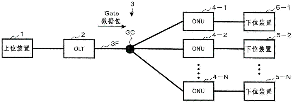
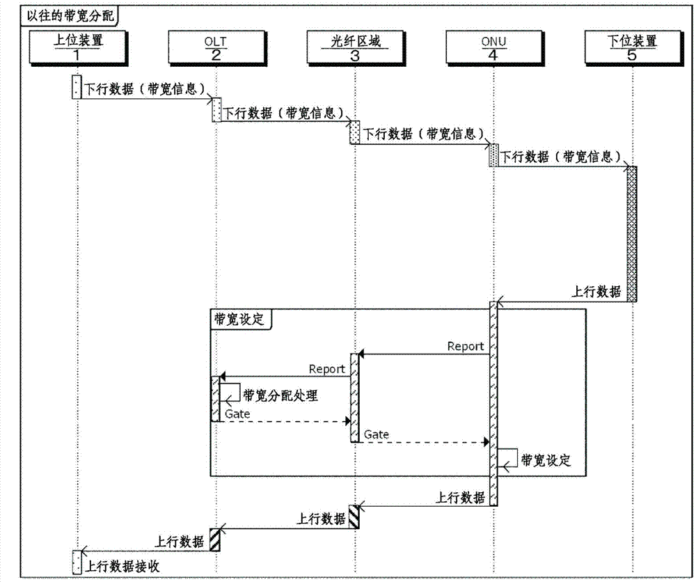
technical field [0001] The present invention relates to a technique for high-speed transmission of uplink data from a lower device to a higher device in a communication system composed of a higher device and a lower device connected through an optical subscriber system (PON: Passive Optical Network). Background technique [0002] The economical efficiency of the optical user system using the passive double-star structure is high, so the GE-PON system and the G-PON system are widely promoted in the world, and the high-speed 10G-EPON system and the XG-PON system are also constantly being developed. Research. [0003] Picture 1-1 and diagram 2-1 The structure of the conventional optical subscriber communication system is shown. The optical subscriber communication system includes: a host device 1, an optical subscriber line terminal unit (OLT: Optical Line Terminal) 2, an optical fiber section 3 composed of an optical fiber 3F and an optical coupler 3C, and an optical subsc...

Claims


Application Information

Patent Timeline
Patent Type & Authority Applications(China)
IPC IPC(8): H04L12/44
CPCH04Q11/0067H04L12/2861H04Q2011/0064H04B10/27H04B10/25752H04J14/08
Inventor 桑野茂寺田纯饭山法子坂本健田中伸幸重松智志
Owner NIPPON TELEGRAPH & TELEPHONE CORP
Learn More