[0026] The principles and features of the present invention will be described below with reference to the accompanying drawings. The examples are only used to explain the present invention, but not to limit the scope of the present invention.
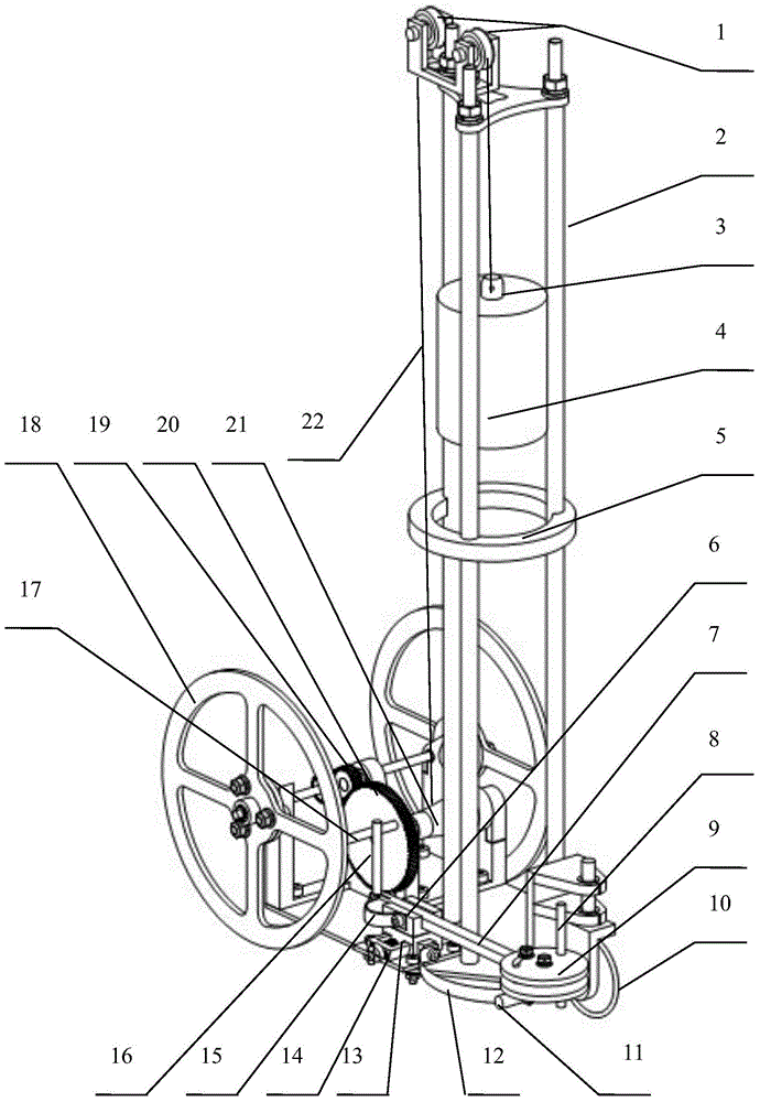
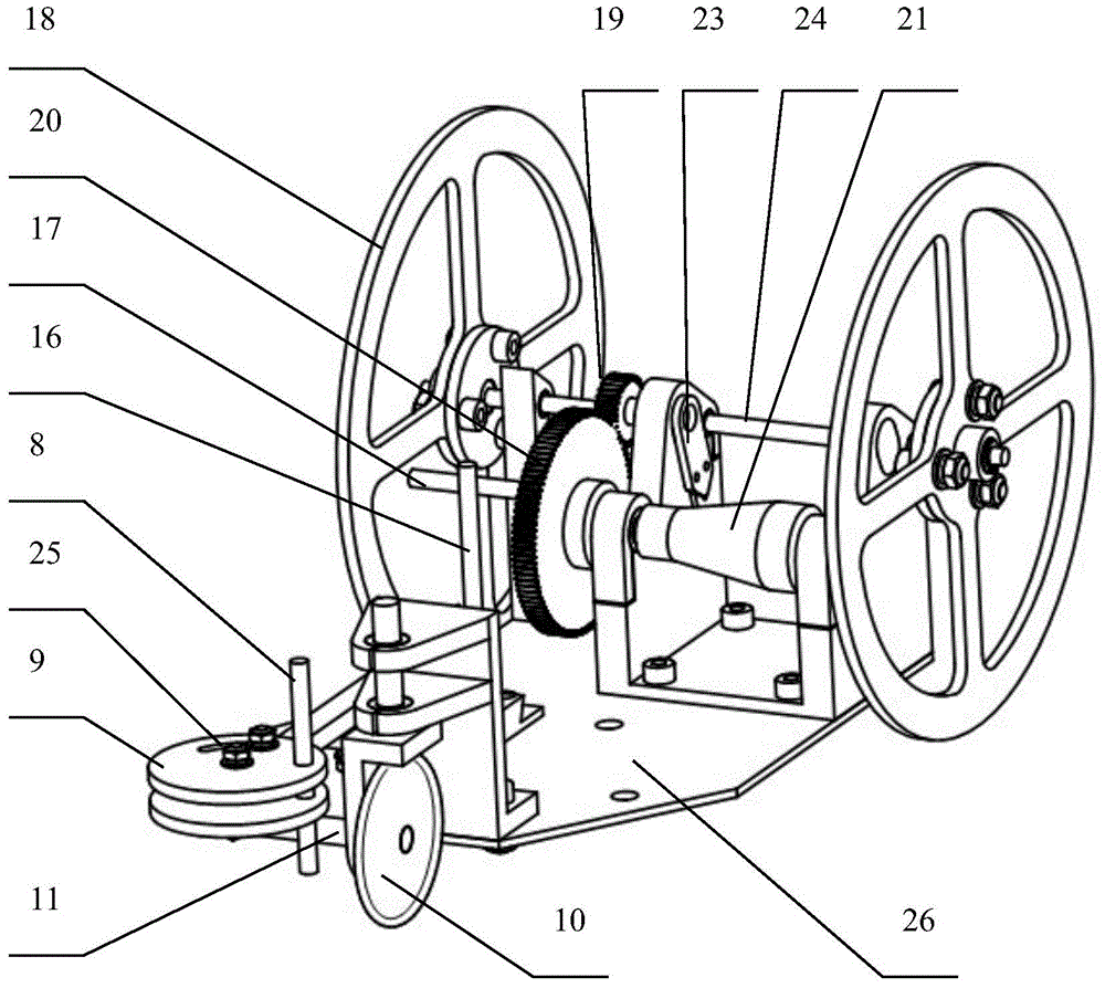
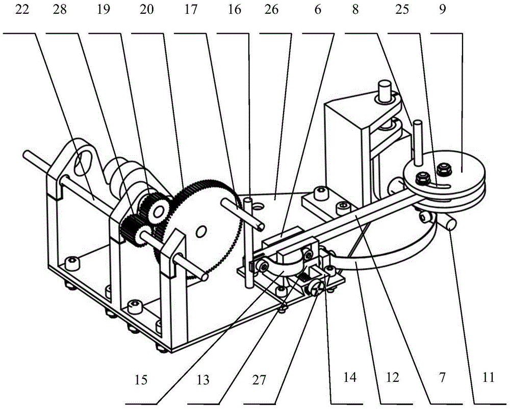
[0027] like figure 1 As shown, the carbon-free trolley that can adapt to the S-shaped path of different rod distances, its three uprights 2 are assembled on the bottom plate 26 of the car body (see figure 2 ), the top of the three uprights 2 is a pulley seat, two pulleys 1 are placed on the pulley seat, the weight 4 is lifted to a certain height, and is tied on the flexible wire rope 22 through the hook 3, and the flexible wire rope 22 is wound around two On the pulley 1, and then tied to the wire pulley 21 at the lower part of the vehicle body, a flexible wire rope 22 of sufficient length is wound around the wire pulley 21, so that when the heavy object 4 falls, the flexible wire rope 22 wound on the wire pulley 21 can drive the wire Wheel 21 turns.
[0028] The snap ring 5 located in the middle section of the column 2 plays a stable role on the three columns.
[0029] The driving mechanism for driving the rear wheel consists of the wire wheel 21, the main gear 20, the adjusting gear 19, and the slave gear 28 that drives the rear wheel 18 to rotate (see image 3 ), rear axle 24 (see figure 2 ) and two rear wheels 18 arranged at both ends of the rear wheel axle 24. The wire pulley 21 is coaxial with the main gear 20, the slave gear 28 is arranged on the rear axle 22, the adjustment gear 19 is located between the main gear 20 and the slave gear 28, the master gear 20 meshes with the adjustment gear 19, and the adjustment gear 19 meshes with the slave gear 28.
[0030] The master gear 20, the slave gear 28 and the adjusting gear 19 together constitute a pitch changing mechanism.
[0031] The steering mechanism consists of the rear ejector rod 16, the front ejector rod 8, the push rod 7, the adjusting disc 9, the push rod spring 15 and the front axle spring 12, as well as the eccentric ejector column 17, the front wheel 10 and the front wheel axle set on the main gear 20 11 constitute together.
[0032] See figure 2. The adjusting gear 19 is arranged in a strip-shaped groove on the frame and is fixed by the flange bearing 23 . The bar slot is covered and not directly visible in the picture. In order to adapt to different rod distances, only one slave gear 28 needs to be replaced, and the position of the adjusting gear 19 is adjusted so that the three gears (the main gear 20, the adjusting gear 19 and the slave gear 28) are meshed. The position of the adjusting gear 19 can be adjusted freely by setting the bar-shaped groove to ensure the meshing of the three gears.
[0033] like image 3 As shown, in the steering mechanism, an eccentric top column 17 is provided on the main gear 20 of the driving mechanism, the rear top rod 16 is arranged at the rear end of the push rod 7, the front end of the push rod 7 is connected to the adjusting plate 9, and the front top rod 8 is arranged on the adjusting plate. The edge position of 9; the front ejector rod 8 is kept in contact with the front wheel axle 11 due to the action of the front axle spring 12, and the rear ejector rod 16 is kept in contact with the eccentric ejector column 17 due to the action of the push rod spring 15; On the bracket 14 of the underbody 26, the bracket 14 is provided with the sliding seat 6 in which the push rod 7 slides, the fixing points of the front axle spring 12 and the push rod spring 15 are located on the sliding seat 6, the push rod spring 15 and the front The axle springs 12 are all spring sheets.
[0034] A sliding plate 13 is arranged between the sliding seat 6 and the bracket 14 , the sliding seat 6 is arranged on the sliding plate 13 , and a device for adjusting the lateral movement of the sliding plate 13 is arranged on the bracket 14 . This device is the screw device adjusted by the screw adjuster 27 . The screw device and the sliding plate 13 constitute a lateral adjustment mechanism for laterally moving the steering mechanism. By rotating the screw adjuster 27, the screw is rotated forward and reverse, thereby driving the sliding plate 13 to move left and right, so as to realize the lateral movement of the entire steering mechanism.
[0035] A fine adjustment groove 25 is opened on the adjustment disc 9 , and the connection point between the front end of the push rod 7 and the adjustment disc 9 is located in the fine adjustment slot 25 .
[0036] When working, tie the weight 4 on the flexible wire rope 22 through the hook 3, lift the weight 4 to the specified height, the flexible wire rope 22 is wound on the two pulleys 1, and then tied down to the wire wheel at the lower part of the vehicle body. 21, a long enough flexible cord 22 is wound around the reel 21, so that the flexible cord 22 is taut. Then the weight 4 falls by itself under the action of gravity, the flexible wire rope 21 tied to the weight 4 changes the direction of the pulling force through the pulley 1 installed on the pulley seat, and the other end of the wire rope 21 drives the wire pulley 21 to rotate, and The coaxial main gear 20 also rotates together, the meshed adjusting gear 19 and the slave gear 28 also rotate, and the rear axle 24 rotates with the slave gear 28, so that the two rear wheels 18 installed at both ends of the rear axle 24 rotate, making the trolley go ahead.
[0037] At the same time, the eccentric top post 17 on the main gear 20 makes a circular motion, and the rear top rod 16 keeps in contact with the eccentric top post 17 under the action of the push rod spring 15, so that the rear top rod 16 will move back and forth, Push the push rod 7 to slide back and forth in the sliding seat 6, and the push rod 7 makes the adjustment plate 9 and the front ejector rod 8 fixed on the adjustment disk 9 to move forward and backward in a straight line. It keeps in contact with the front axle 11 all the time, so the front and rear movement of the front ejector rod 8 causes the front axle 11 to swing back and forth, and as a result, the front wheel 10 swings left and right, thereby making the car turn.
[0038] When the screw adjuster 27 is rotated, the screw connected to it will rotate in the forward or reverse direction. Institutions also move laterally. As a result, the contact position between the front ejector rod 8 and the front wheel axle 11 changes, that is, the distance between the contact point and the front wheel 10 becomes longer or shorter, and the change of this distance changes the swing angle of the front wheel axle 11, which also changes the The swing angle of the front wheel 10 produces a difference in the size of the steering action of the trolley.
[0039] On the other hand, changing the position of the connection point between the front end of the push rod 7 and the adjustment plate 9 in the fine adjustment groove 25 of the adjustment plate 9 also changes the stroke length of the push rod 7 and changes the relative relationship between the front push rod 8 and the push rod 7 Position, the size of the swing angle of the front wheel 10 can also be changed, so as to realize the fine adjustment of the steering size of the trolley.
[0040] The above are only preferred embodiments of the present invention and are not intended to limit the present invention. Any modifications, equivalent replacements, improvements, etc. made within the spirit and principles of the present invention shall be included in the protection of the present invention. within the range.