High pressure cleaning machine
A high-pressure cleaning machine and cleaning machine technology, which are applied in cleaning methods and utensils, cleaning methods using liquids, chemical instruments and methods, etc., to achieve the effects of cost saving and convenient switching
- Summary
- Abstract
- Description
- Claims
- Application Information
AI Technical Summary
Problems solved by technology
Method used
Image
Examples
Embodiment 1
[0039] Such as figure 2 As shown, in order to realize that the voltage that the controller can provide to the motor M1 is at least U11 or U21, in this embodiment, a rectifier circuit is used in the controller, including a rectifier bridge D1, and the two output terminals of the rectifier bridge D1 Respectively connected to the two ends of the resistor R1, the resistor R1 is connected in parallel to the two ends of the motor M1, and the two ends of the resistor R1 are also connected in parallel with the capacitors C1 and C2 to rectify the rated AC input voltage into DC, so that the output voltage of the controller can be rated AC input voltage U11 or DC voltage U21.
Embodiment 2
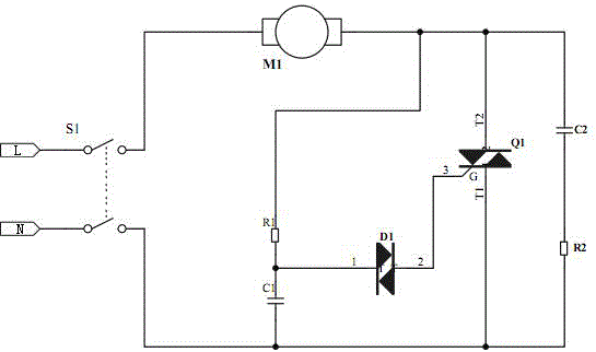
[0041] Such as image 3 As shown, in order to realize that the voltage that the controller can provide to the motor M1 is at least two states of U12 or U22, in this embodiment, a chopper circuit controlled by the linkage switch S1 is used in the controller to convert the rated AC input voltage U22 through Step-up chopping or step-down chopping into another AC voltage U21, so that the output voltage of the controller can be U12 or AC voltage U22. The chopper circuit includes a diac Q1 and a diac D1 connected to the control terminal G of the diac Q1, and two branches are connected in parallel at both ends of the diac Q1, which are respectively a series capacitor C1 and a resistor R1 branch and a series circuit The capacitor C2 and resistor R2 branch. One end of the bidirectional trigger diode D1 is connected to the control terminal G of the bidirectional trigger diode Q1, and the other end is connected to the common junction of the capacitor C1 and the resistor R1.
Embodiment 3
[0043] Such as Figure 4As shown, in order to realize that the voltage that the controller can provide to the motor M1 is at least two states of U13 or U23, in this embodiment, a rectifier circuit and an inductive boost circuit are used in the controller to rectify the rated AC input voltage into DC After boosting by the inductance booster circuit, the output voltage of the controller can be the rated AC input voltage U13 or DC voltage U23, and U13<U23. Wherein, the rectification circuit includes a rectification bridge D1, the two output ends of the rectification bridge D1 are respectively connected to the two ends of the resistance R1, and the two ends of the resistance R1 are also connected in parallel with capacitors C1 and C2 to rectify the rated AC input voltage into DC. One end of the resistor R1 is connected to the anode of the diode D2 through the inductance L1, the cathode of the diode D2 is connected to one end of the motor M1, the other end of the motor M1 and the o...
PUM
 Abstract
Description
Claims
Application Information
 - R&D
- Intellectual Property
- Life Sciences
- Materials
- Tech Scout
- Unparalleled Data Quality
- Higher Quality Content
- 60% Fewer Hallucinations
Browse by: Latest US Patents, China's latest patents, Technical Efficacy Thesaurus, Application Domain, Technology Topic, Popular Technical Reports.
© 2025 PatSnap. All rights reserved.Legal|Privacy policy|Modern Slavery Act Transparency Statement|Sitemap|About US| Contact US: help@patsnap.com


