
A high pressure washer

A high-pressure cleaning machine and cleaning machine technology, applied in cleaning methods and utensils, cleaning methods using liquids, chemical instruments and methods, etc., to achieve the effect of convenient switching and cost saving

Active Publication Date: 2017-11-21
SUMEC HARDWARE & TOOLS
View PDF7 Cites 0 Cited by
  • Summary
  • Abstract
  • Description
  • Claims
  • Application Information

AI Technical Summary

Problems solved by technology

[0003] The technical problem to be solved by the present invention is to overcome the defects of the prior art and provide a high-pressure cleaning machine, which solves the problem that the same high-pressure cleaning machine can realize high pressure and low flow parameters, and at the same time realize low pressure and large flow parameters, It enables users to easily choose different parameter functions of the cleaning machine according to the needs of different use environments. The switching is convenient and reliable, and meets the various needs of users.

Method used


Image

  • A high pressure washer
  • A high pressure washer
  • A high pressure washer

Examples


Embodiment 1

[0039] Such as figure 2 As shown, in order to realize that the voltage that the controller can provide to the motor M1 is at least U11 or U21, in this embodiment, a rectifier circuit is used in the controller, including a rectifier bridge D1, and the two output terminals of the rectifier bridge D1 Respectively connected to the two ends of the resistor R1, the resistor R1 is connected in parallel to the two ends of the motor M1, and the two ends of the resistor R1 are also connected in parallel with the capacitors C1 and C2 to rectify the rated AC input voltage into DC, so that the output voltage of the controller can be rated AC input voltage U11 or DC voltage U21.

Embodiment 2

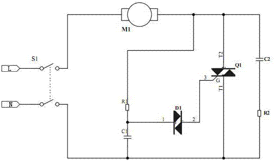
[0041] Such as image 3 As shown, in order to realize that the voltage that the controller can provide to the motor M1 is at least two states of U12 or U22, in this embodiment, a chopper circuit controlled by the linkage switch S1 is used in the controller to convert the rated AC input voltage U22 through Step-up chopping or step-down chopping into another AC voltage U12, so that the voltage output by the controller can be U12 or AC voltage U22. The chopper circuit includes a diac Q1 and a diac D1 connected to the control terminal G of the diac Q1, and two branches are connected in parallel at both ends of the diac Q1, which are respectively a series capacitor C1 and a resistor R1 branch and a series circuit The capacitor C2 and resistor R2 branch. One end of the bidirectional trigger diode D1 is connected to the control terminal G of the bidirectional trigger diode Q1, and the other end is connected to the common junction of the capacitor C1 and the resistor R1.

Embodiment 3

[0043] Such as Figure 4As shown, in order to realize that the voltage that the controller can provide to the motor M1 is at least two states of U13 or U23, in this embodiment, a rectifier circuit and an inductive boost circuit are used in the controller to rectify the rated AC input voltage into DC After boosting by the inductance booster circuit, the output voltage of the controller can be the rated AC input voltage U13 or DC voltage U23, and U13<U23. Wherein, the rectification circuit includes a rectification bridge D1, the two output ends of the rectification bridge D1 are respectively connected to the two ends of the resistance R1, and the two ends of the resistance R1 are also connected in parallel with capacitors C1 and C2 to rectify the rated AC input voltage into DC. One end of the resistor R1 is connected to the anode of the diode D2 through the inductance L1, the cathode of the diode D2 is connected to one end of the motor M1, the other end of the motor M1 and the o...


PUM


Abstract

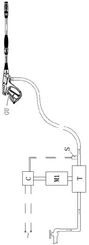
The invention discloses a high pressure cleaning machine which comprises a motor, a water pump, a high pressure gun, a controller and a sensor. The controller controls input voltages of the motor, and the sensor is arranged at a water outlet of the water pump. The controller provides different input voltages for the motor according to signals detected by the sensor. When the controller provides the voltage U1, the corresponding output working rotating speed of the motor is N1, and corresponding output parameters, namely pressure and flow of the water pump are P1 and Q1; when the controller provides the voltage U2, the corresponding output working rotating speed of the motor is N2, and corresponding output parameters, namely pressure and flow of the water pump are P2 and Q2; if U1 is set to be smaller than U2, N1 is smaller than N2, P1 is smaller than P2, and Q1 is smaller than Q2. High-pressure and low-flow parameters and low-pressure and high-flow parameters can be obtained on the same high pressure cleaning machine, and only the input voltages of the motor need to be adjusted, so that the magnitude of the flow of the water pump driven by the motor is adjustable, the using requirement of a user is met, switching is convenient and reliable, and the cost is saved.

Description

technical field [0001] The invention relates to a high-pressure cleaning machine, in particular to a high-pressure cleaning machine with multiple sets of pressure and flow cleaning parameters. Background technique [0002] In the high-pressure cleaner industry, especially household electric cleaners, the pressure and flow are restricted by the power of the motor, and the power of the motor is mainly limited by the maximum power (maximum current) of household electricity, the actual cleaning capacity and cleaning range cannot In the best condition, when encountering local dirt that is difficult to clean, it is necessary to use high pressure to improve the cleaning effect; when encountering easy-to-clean pipes or floors, it is necessary to use large flow to improve cleaning efficiency. In the prior art, in order to obtain high pressure, the motor power is often designed to the maximum allowable power value. When a large flow rate is required, the pressure is reduced and the fl...

Claims


Application Information

Patent Timeline
Patent Type & Authority Patents(China)
IPC IPC(8): B08B3/02B08B13/00
CPCB08B3/02B08B13/00B08B2203/027
Inventor 陈伟黄其庆
Owner SUMEC HARDWARE & TOOLS
Learn More