Movable shearing cutter rest for cloth cutting machine

A cutting machine, mobile technology, applied in the cutting of textile materials, textiles and papermaking, metal processing, etc., can solve the problems of inaccurate cutting positioning, troublesome cutting, not neat enough cuts, etc., and achieve good cutting effect , good flexibility and neat incision

Active Publication Date: 2015-07-22
刘骏
View PDF6 Cites 29 Cited by
  • Summary
  • Abstract
  • Description
  • Claims
  • Application Information

AI Technical Summary

Problems solved by technology

[0002] After the fabric is processed, it needs to be sampled or cut. The existing fabric cutting method generally uses scissors for manual cutting, which is troublesome to cut, and the cut is not neat enough and the precision is

Method used


Image

  • Movable shearing cutter rest for cloth cutting machine
  • Movable shearing cutter rest for cloth cutting machine
  • Movable shearing cutter rest for cloth cutting machine

Examples


Embodiment Construction

[0019] The present invention will be described in detail below in conjunction with accompanying drawings and specific preferred embodiments, so that the advantages and features of the present invention can be more easily understood by those skilled in the art. range is limited.

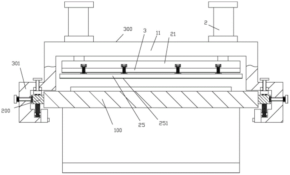
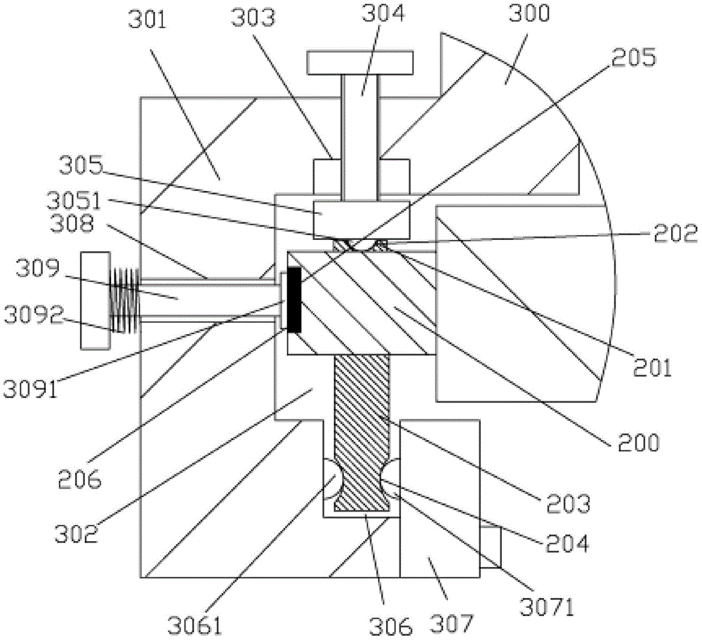
[0020] Examples, see e.g. Figure 1 to Figure 5 As shown, a movable cutting blade frame of a cloth cutting machine includes a frame platen 100, and sliding bars 200 are fixed on the left and right side walls of the frame platen 100, and the top surface of the sliding bar 200 is fixed Limiting block 201, the top surface of limiting block 201 has arc-shaped long groove 202, the bottom surface of sliding bar 200 is fixed with bottom sliding block 203, and the left and right sides of bottom sliding block 203 has the main length that is arc-shaped. Groove 204, the elongated groove 205 that has on the left side wall of slide bar 200 or the right side wall is nested and is fixed with permanent magnet bar 20...


PUM


Abstract

The invention discloses a movable shearing cutter rest for a cloth cutting machine. The movable shearing cutter rest comprises a rack platen. Sliding strips are fixed to the left side wall and the right side wall of the rack platen. Limiting blocks are fixed to the top faces of the sliding strips. Long grooves with arc-shaped sections are formed in the top faces of the limiting blocks. Bottom sliding blocks are fixed to the bottom faces of the sliding strips. Long main grooves with arc-shaped sections are formed in the left side and the right side of each bottom sliding block. Permanent magnet strips are embedded in the long grooves in the left side walls or the right side walls of the sliding strips. A cutter moving rest is inserted in the rack platen. Sliding parts shaped like a left square bracket are arranged on the left side and the right side of the cutter moving rest. Push cylinders are fixed to a top transverse board of the cutter moving rest. Push rods of the push cylinders penetrate through the top transverse board downwards and a strip-shaped board is fixed to the push rods. The cutter moving rest can move along the rack platen so as to be move to the position needing to be sheared. The movable shearing cutter rest is good in flexibility, cloth can be fixed and pushed by the push cylinders so as to be sheared, notches are tidy, and efficiency is high.

Description

Technical field: [0001] The invention relates to the technical field of textile equipment, in particular to a movable cutting tool holder of a cloth cutting machine. Background technique: [0002] After the fabric is processed, it needs to be sampled or cut. The existing fabric cutting method generally uses scissors for manual cutting, which is cumbersome to cut, and the cut is not neat enough and the precision is poor. Therefore, there is a mechanism of mechanical shearing now, but the fixed position of the shearing tool cannot be adjusted, so that the flexibility is poor during use, and the problem of inaccurate positioning of shearing occurs. Invention content: [0003] The purpose of the present invention is to overcome the deficiencies of the prior art, and provide a movable cutting knife frame of a cloth cutting machine, its knife moving frame can move along the frame platen, so that it can move to the place where cutting is required , good flexibility, at the same ...

Claims


Application Information

Patent Timeline
IPC IPC(8): B26D7/26B26D7/02D06H7/00
Inventor 马根生
Owner 刘骏
Why Eureka
Try Eureka