Method for enabling metal insert to be moulded through injection moulding and injection product containing metal insert

A metal insert and injection molding technology, applied in the direction of coating, etc., can solve the problems of insufficient injection molding, increased production cost, limited application range, etc., and achieve the goals of avoiding insufficient injection molding or overflowing glue, simplifying the bonding structure, and simplifying the bonding structure Effect

Inactive Publication Date: 2015-07-22
PERLOSGUANGZHOU ELECTRONICS COMPONENTS +1
View PDF3 Cites 15 Cited by
  • Summary
  • Abstract
  • Description
  • Claims
  • Application Information

AI Technical Summary

Problems solved by technology

[0004] However, the above-mentioned processing method for enhancing firmness, due to the design and manufacture of complex structures such as buckles and bolts on the metal insert, the metal processing cycle becomes longer and the production cost increases, and the complex structure is difficult to appl

Method used


Image

  • Method for enabling metal insert to be moulded through injection moulding and injection product containing metal insert
  • Method for enabling metal insert to be moulded through injection moulding and injection product containing metal insert
  • Method for enabling metal insert to be moulded through injection moulding and injection product containing metal insert

Examples


Embodiment 1

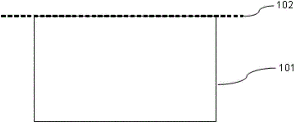
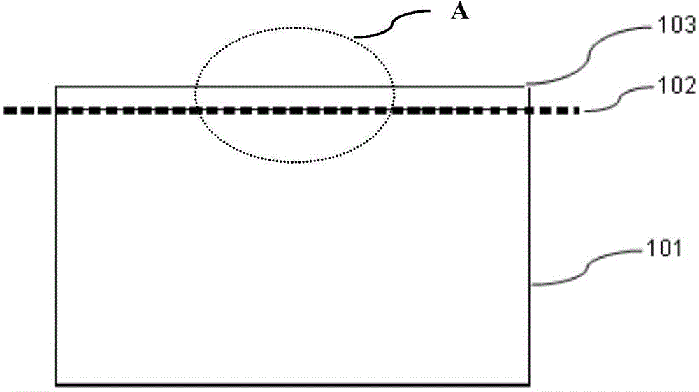
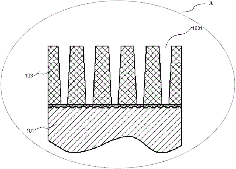
[0035] refer to Figure 1a~1c , figure 2 , the present invention provides an injection molding product of a metal insert, which includes: a metal insert 101 and a plastic 104 after surface treatment.

[0036] Such as Figure 1a It is a schematic diagram of the structure of the metal insert 101 without anodic oxidation treatment. The surface of the metal insert 101 is anodized to form a film layer 103 with a thickness of about 5-7 μm (refer to Figure 1b ); Figure 1c yes Figure 1b Enlarged view of part A in Fig. Such as Figure 1c As shown, the film layer 103 has a hole 1031 inside and the hole 1031 is filled with an adhesion treatment agent (not shown). The depth of the hole is 1-10 μm, and the pore diameter is 5-30 nm.

[0037] The plastic 104 is combined with the metal insert 101 , and a part of the plastic 104 enters the hole 1031 and is combined with the metal insert 101 through the adhesion treatment agent.

[0038] The injection molded product of the metal inse...

Embodiment 2

[0082] The difference between embodiment 2 and embodiment 1 is: in embodiment 2, such as image 3 As shown, the metal insert 301 of the injection molding product of the metal insert and the film layer 303 are concave on the surface at the junction to form a concave hole 3011 communicating with the hole 3031 in the film layer 303, and the concave hole 3011 is also filled with adhesion treatment agent (not shown), the plastic part continues to enter the concave hole 3011 and is combined with the metal insert 301 through the adhesion treatment agent.

[0083] In this embodiment, the difference between the manufacturing method of the injection molding product of the metal insert and Embodiment 1 is that:

[0084] Please refer to image 3 , Figure 4After performing the anodizing treatment and before performing the adhesion treatment, the metal insert 301 is also subjected to hole expansion treatment, specifically, the metal insert 301 after the anodic oxidation treatment is imme...


PUM

PropertyMeasurementUnit
Thicknessaaaaaaaaaa
Depthaaaaaaaaaa
Apertureaaaaaaaaaa

Abstract

The invention provides a method for enabling a metal insert to be moulded through injection moulding and an injection product containing the metal insert. The method comprises: performing pre-treatment to the metal insert having a pre-set shape to make the surface of the metal insert clean; performing anodic oxidation treatment to the metal insert after the pre-treatment to allow a film layer with a thickness of 1-8 mum to be formed on the surface of the metal insert, wherein holes with irregular shapes are formed in the film layer; performing adhesion treatment to the metal insert containing the holes by using an adhesion treatment agent; and carrying out injection moulding to the metal insert after the adhesion treatment to enable the metal insert to be directly combined with a plastic through flat surfaces. According to the invention, a combination structure of a metal and a plastic is effectively simplified; the manufacture cost is lowered; and the production efficiency and the yield are improved.

Description

technical field [0001] The invention belongs to the technical field of metal insert molding, and in particular relates to a method for injection molding a metal insert and an injection molded product of the metal insert. Background technique [0002] In insert molding technology, especially in the field of manufacturing and application of electronic handheld device casings, more and more insert molding technologies use metal as an injection molding insert (insert) to be placed in the mold, through The injection molding machine injects plastic into the mold to form an integral body with the metal insert. [0003] In order to make the combination of metal and plastic more firm and reliable, generally before injection molding and during the processing of metal inserts, the metal will be designed and manufactured into a certain shape structure, such as designing and manufacturing buckle structure and bolt structure on the metal etc., so that the plastic flows during the injecti...

Claims


Application Information

Patent Timeline
IPC IPC(8): B29C45/14B29C45/17B29B11/00
CPCB29B11/00B29C45/14008B29C45/17
Inventor 蔡舜任洪梁刘叔珍陈汉坚杨宇昊罗梦秋张松
Owner PERLOSGUANGZHOU ELECTRONICS COMPONENTS
Why Eureka
Try Eureka