Wheel switching mechanism for mobile robot

A mobile robot and switching mechanism technology, applied in motor vehicles, transportation and packaging, etc., can solve the problems of slow walking speed and poor obstacle avoidance ability, and achieve the effects of reducing power consumption, saving processing and assembly costs, and reducing the number of motors

Active Publication Date: 2015-07-22
HARBIN INST OF TECH
View PDF4 Cites 8 Cited by
  • Summary
  • Abstract
  • Description
  • Claims
  • Application Information

AI Technical Summary

Problems solved by technology

[0005] In order to solve the problems of poor obstacle avoidance ability of existing wheeled robots and slow walking speed of existing footed robots, the present invention further provides a wheel foot mechanism for mobile robots

Method used


Image

  • Wheel switching mechanism for mobile robot
  • Wheel switching mechanism for mobile robot
  • Wheel switching mechanism for mobile robot

Examples


specific Embodiment approach 1

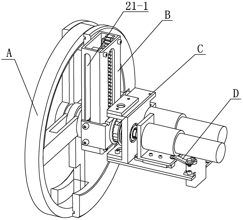
[0017] Specific implementation manner one: such as Figure 1~5 As shown, the wheel-foot conversion mechanism for a mobile robot of this embodiment includes a wheel-foot conversion body A, a lifting mechanism B, a rotating mechanism C, and a switching mechanism D;

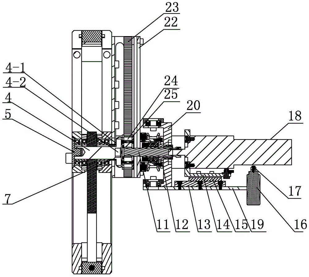
[0018] The wheel foot conversion body A includes a fixed half-wheel 1, a movable half-wheel 2, a single banner 3, a central shaft 4, a first stop block 5 and a spring 6. The central shaft 4 is installed at the center of the fixed half-wheel 1 through a first bearing , One end of the central shaft 4 is fixedly connected and axially locked by the first limit block 5, the other end of the central shaft 4 is provided with a shoulder 4-1, the spring 6 is sleeved on the central shaft 4 and is located on the first bearing Between the shoulder 4-1, the other end of the central shaft 4 is machined with a central blind hole 4-2, the central blind hole 4-2 is machined with a first keyway; the fixed half wheel 1 is machined with a...

specific Embodiment approach 2

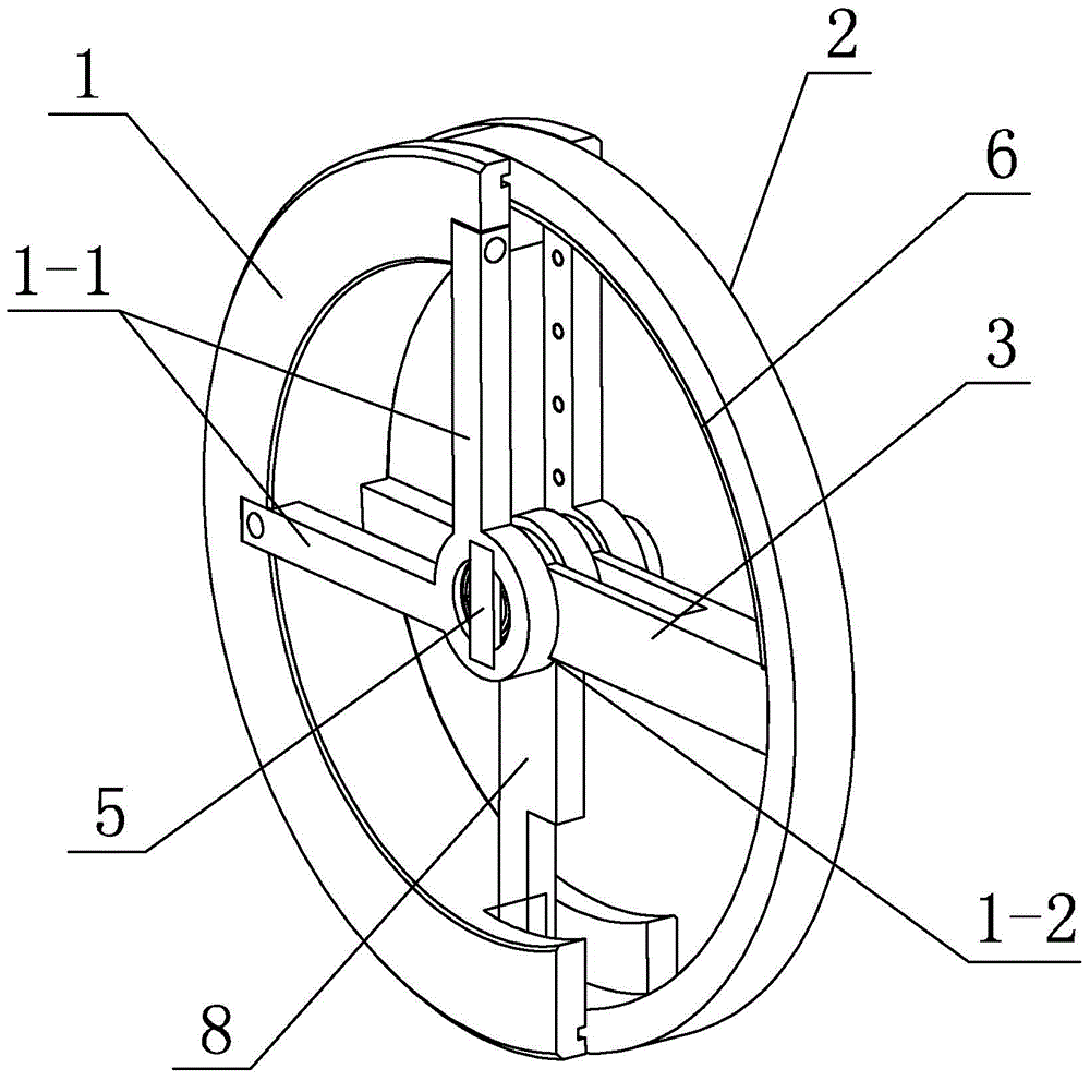
[0022] Specific implementation manner two: such as figure 2 As shown, the fixed half-wheel 1 of this embodiment is provided with two fixed banners 1-1, and the two fixed banners 1-1 are arranged at right angles. With this arrangement, the rigidity of the fixed half-wheel 1 is guaranteed, and serious deformation will not occur under radial force. The fixed banner 1-1 and the fixed half-wheel 1 are designed into two parts, which also reduces the processing time. Difficulty and cost. The other components and connection relationships are the same as in the first embodiment.

specific Embodiment approach 3

[0023] Specific implementation manner three: such as figure 2 As shown, the wheel foot conversion body A of this embodiment includes a baffle 6 and a movable banner 8. The baffle 6 is arranged on the inner wall of the movable half-wheel 2, and the connection between the two fixed banners 1-1 is processed with notches. 1-2. When changing the wheeled state, the single banner 3 is restricted by the notch 1-2 in the horizontal position, the upper end of the single banner 3 is in contact with the baffle 6, and the movable banner 8 is vertically arranged on the wheel foot conversion body A In the lower half, one end of the movable banner 8 is fixedly connected with the central shaft 4, and the other end of the movable banner 8 is fixedly connected with one end of the movable half-wheel 2. With such a design, it is easy to see that the single banner 3 is a follow-up spoke, which can rotate with the movable half wheel 2 when the wheel foot changes, which can improve the rigidity of the...


PUM


Abstract

The invention discloses a wheel foot switching mechanism for a mobile robot, and relates to the wheel foot switching mechanism. The problems that the obstacle avoidance ability of an existing wheeled robot is poor and an existing foot type robot walks slowly are solved. one end of a central shaft is fixedly connected and is locked axially through a first limiting block, the other end of the central shaft is provided with a shoulder, a spring sleeves the central shaft and is arranged between a first bearing and the shoulder, a center blind hole is formed in the other end of the central shaft, and a first key groove is formed in the interior of the center blind hole; a half-ring groove is formed in a fixed half wheel in the peripheral direction of the fixed half wheel, a moving half wheel is connected with the fixed half wheel in a rotating mode relative to the central shaft, when a wheeled type state is switched, a complete wheel is formed by the fixed half wheel and the moving half wheel, when a foot type state is switched, the moving half wheel rotates and is arranged in the half-ring groove of the fixed half wheel, and a single scroll is installed on the central shaft. The invention belongs to the field of the mobile robot.

Description

Technical field [0001] The invention relates to a wheel-foot conversion mechanism, in particular to a wheel-foot conversion mechanism for a mobile robot. The robot can switch between wheel-foot two modes. Background technique [0002] The current disaster relief work is mainly based on manual search and rescue, which greatly limits the level and efficiency of rescue, causing many victims to miss the best treatment time and lose precious lives. Since most of the search and rescue scenes are severely damaged by fire, bombs, water, etc., the ground environment at the scene is extremely complicated, with flat roads and bumpy roads; jungles, grasslands, stairs, and obstacles. These conditions require the robot to be particularly adaptable to the environment, not only to be able to move on a plane, but also to be able to go up and down stairs and climb obstacles. At present, a single footed robot or a single wheeled robot cannot meet the requirements of robots with particularly strong...

Claims


Application Information

Patent Timeline
Patent Type & Authority Applications(China)
IPC IPC(8): B62D57/028
CPCB62D57/028
Inventor 臧希喆孙欣然李长乐朱延河赵杰
Owner HARBIN INST OF TECH
Why Eureka
Try Eureka