Construction method of tunnel steel arch feet-lock bolts

A technology of locking foot bolts and construction methods, which is applied to tunnels, tunnel linings, and installation of bolts, etc. It can solve problems such as delays in the construction period, exceeding the reserved value, and increased construction costs, so as to avoid random operation and accurate Simple positioning and operation

Inactive Publication Date: 2015-07-22
CHINA RAILWAY 21ST BUREAU GROUP THE FOURTH ENG
View PDF5 Cites 15 Cited by
  • Summary
  • Abstract
  • Description
  • Claims
  • Application Information

AI Technical Summary

Problems solved by technology

Due to the fact that there is no corresponding standard for the scope of use and installation of the lock-foot bolt, and the concept of the penetration angle has not been established. During the construction of the tunnel bolt-spray support, the entry of the lock-foot bolt seems to be relatively random, and there is no relatively certain The operation specification allows the on-site construction personnel to easily control the driving angle of the locking anchor bolt, which makes the tunnel vault sink and the horizontal convergence is relatively large, exceeding the reserved value, so that the anchor shotcrete support invades the limit of the second concrete lining In this way, the thickness of the concrete secondary lining is affected, leaving a safety hazard for the later construction and operation of the tunnel; or if the arch replacement treatment is performed before the concrete secondary lining, there will still be certain safety hazards during the arch replacement treatment, and it will also cause The increase of construction cost and the delay of construction period
In the current tunnel construction, there is no better construction method that can change this situation, and there are no public reports on related improved technologies

Method used


Image

  • Construction method of tunnel steel arch feet-lock bolts
  • Construction method of tunnel steel arch feet-lock bolts

Examples


Embodiment Construction

[0017] Below in conjunction with embodiment and accompanying drawing, the present invention is described in further detail:

[0018] Specific embodiments of the present invention are as follows:

[0019] a. After the excavation of the tunnel is completed, first spray concrete on the rock wall of the tunnel to seal the rock face, avoid long-term exposure of the rock face, and fill the uneven rock wall generated during excavation;

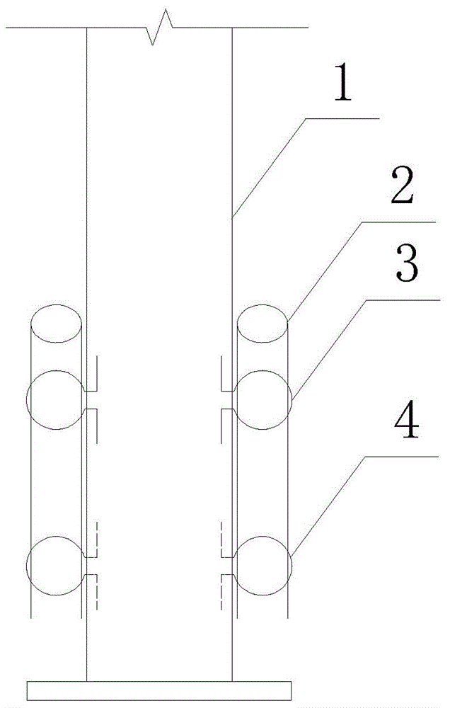
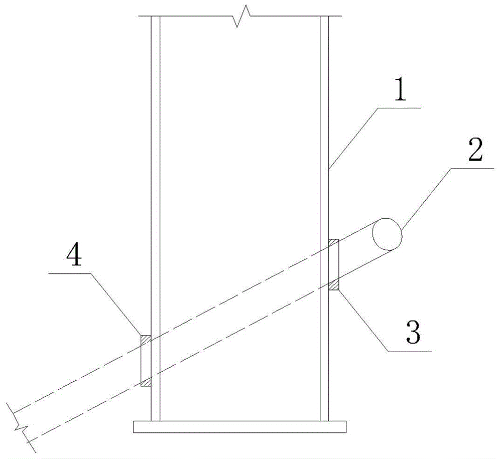
[0020] b. According to the determined angle of the anchor bolt (1) driven into the rock wall of the tunnel, two low-position positioning rings (3) are welded on one side of the steel arch (2), and two high-position positioning rings (3) are welded on the other side of the steel arch (2) 3), the positioning ring (3) is made of Φ22 steel bar and processed into an Ω shape; the distance between the high position positioning ring (3) and the connecting plate (4) is 30cm;

[0021] c. Install the steel arch (2) with the positioning ring (3) welded after th...


PUM


Abstract

The invention discloses a construction method of tunnel steel arch feet-lock bolts. According to the technical scheme, the construction method is characterized in that concrete is preliminarily sprayed after a tunnel is excavated; positioning rings are welded to one side of a steel arch according to the angles of the feet-lock bolts driven into a rock wall; the steel arch is installed after the concrete is preliminarily sprayed; holes are punched in the rock wall according to the determined driving angles, and the feet-lock bolts are driven into the rock wall; the two feet-lock bolts driven into the rock wall are firmly welded to the steel arch; concrete cover spraying is conducted. The feet-lock bolt positioning rings are welded to the steel arch in advance, the feet-lock bolts can be accurately driven into the rock wall according to the determined angles which are designed in advance, operation randomness in the feet-lock bolt construction process is avoided, the feet-lock bolts are positioned in advance and accurately, operation is simple, the feet-lock bolts driven into the rock wall can truly achieve the better effect, and it is guaranteed that the feet-lock bolts and the steel arch are welded and anchored to the tunnel rock wall.

Description

technical field [0001] The invention relates to a construction method of a tunnel lock foot anchor in road and bridge construction, in particular to a construction method of a tunnel steel arch lock foot anchor, which belongs to the field of road and bridge construction. Background technique [0002] In tunnel construction, according to the different types of tunnel rocks and excavation sections, tunnel excavation can be divided into full-section method, upper and lower steps method, partial excavation method and other construction methods. According to the principle of the New Austrian Method, as the permanent lining of the tunnel, the bolt-spray support is generally considered to be used in surrounding rocks of grade III and above; as the flexible support, the shotcrete support has a large amount of deformation, and its outer contour should Leave a slightly larger space, about 20cm or more; the support must be in firm contact with the surrounding rock mass in a large area,...

Claims


Application Information

Patent Timeline
Patent Type & Authority Applications(China)
IPC IPC(8): E21D11/00E21D11/10
CPCE21D11/00E21D11/105E21D20/00
Inventor 黄宏斌何海洋赵宁川史玲天刘党朝
Owner CHINA RAILWAY 21ST BUREAU GROUP THE FOURTH ENG
Why Eureka
Try Eureka