Valve electro-hydraulic driving system and method for achieving Miller cycle of engine

A Miller cycle and engine technology, applied in engine components, combustion engines, machines/engines, etc., can solve problems such as not meeting the optimal performance of the engine and unsuitable for the application of Miller cycle, and achieve the maximum lift controllable, maximum Stable lift opening and less impact on seating

Inactive Publication Date: 2015-07-22
HARBIN ENG UNIV
View PDF5 Cites 5 Cited by
  • Summary
  • Abstract
  • Description
  • Claims
  • Application Information

AI Technical Summary

Problems solved by technology

[0004] The previous variable valve drive technology cannot satisfy the optimal engine p

Method used


Image

  • Valve electro-hydraulic driving system and method for achieving Miller cycle of engine
  • Valve electro-hydraulic driving system and method for achieving Miller cycle of engine
  • Valve electro-hydraulic driving system and method for achieving Miller cycle of engine

Examples


Embodiment Construction

[0020] The present invention is described in more detail below in conjunction with accompanying drawing example:

[0021] Combined with Figures 1 to 4, the system consists of the following four main parts, crankshaft position sensor, electronic control unit (ECU), electro-hydraulic fully variable valve drive mechanism, and valve displacement sensor. Among them, the crankshaft position sensor is a commercially available Hall effect sensor, which is used to measure the position of the bottom dead center (BDC) of the crankshaft; the core component of the electronic control unit is a single-chip microcomputer using Freescale 9S12 series; the fully variable electro-hydraulic drive mechanism mainly includes Feedback chamber composed of high-pressure fuel tank, low-pressure fuel tank, two-position three-way solenoid valve V1, normally open solenoid valve V2, conical slide valve Vc, and a propulsion chamber composed of main piston P1 and feedback piston P2 (P1P2 rigidly connected); Th...


PUM


Abstract

The invention provides a valve electro-hydraulic driving system and method for achieving Miller cycle of an engine. A crankshaft position sensor is connected with an ECU, the ECU is connected with a two-position three-way electromagnetic valve and a normally-open electromagnetic valve, the two-position three-way electromagnetic valve is connected with a high-pressure oil tank, a low-pressure oil tank and a conical slide valve, a feedback piston cylinder is fixed to a main piston cylinder, a feedback piston and a main piston are fixedly connected through a piston rod, the main piston is connected with an inlet valve, a spring is installed between the main piston and the main piston cylinder below the main piston, the conical slide valve is connected with an upper feedback cavity, a main upper cavity and a main lower cavity, a limiting hole is formed in the main lower cavity, the normally-open electromagnetic valve is connected with the upper feedback cavity, and the limiting hole and the normally-open electromagnetic valve are connected with the low-pressure oil tank through the same pipeline. The system and method are used for achieving Miller cycle of the engine, and technology universality and transferability are high.

Description

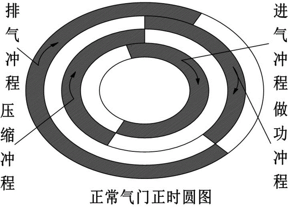
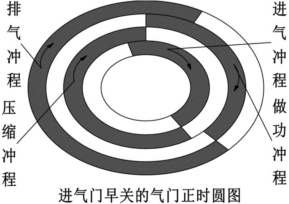
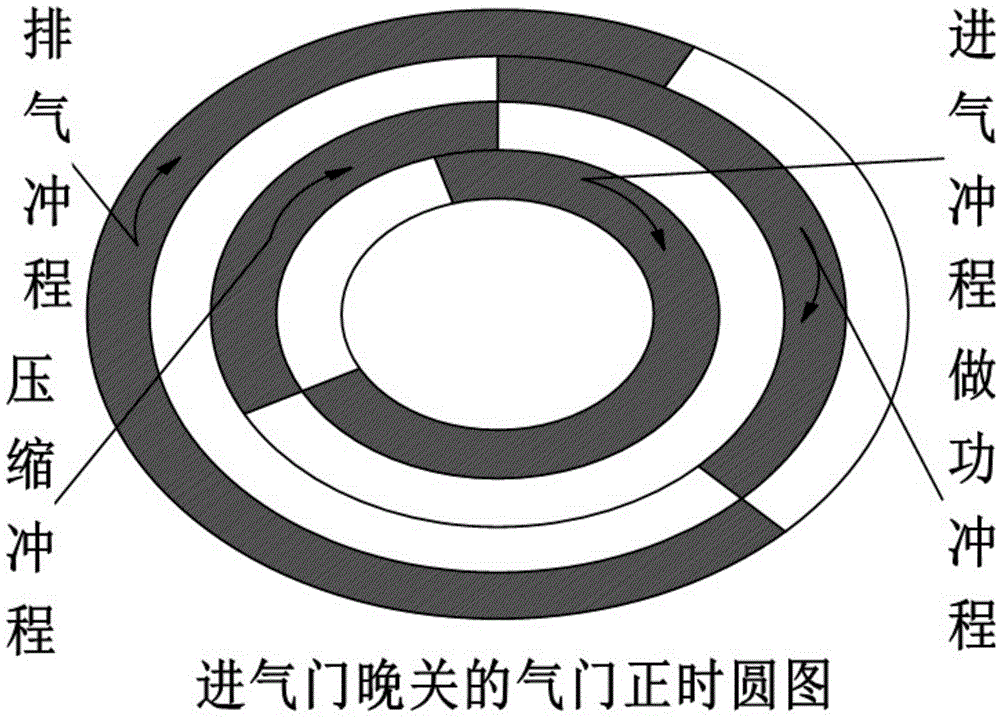
technical field [0001] The invention relates to a valve device of an engine and a driving method thereof. Background technique [0002] In today's increasingly serious environmental problems, engine emission control, especially the reduction of NOX emission is one of the current research hotspots. [0003] The prior art shows that the engine using the Miller cycle can effectively reduce NOX emissions. In fact, the Miller cycle is an improvement of the Otto cycle, not a new heat engine cycle. It has two realization forms, namely: early closing of the intake valve and late closing of the intake valve. a, Early intake valve closing: Before the piston reaches the bottom dead center, the intake valve is closed in advance to stop the intake, reduce the fresh impulse entering the cylinder, and let the fresh impulse expand and cool the cylinder during the intake stroke. Then it is compressed, and the compression ratio is reduced due to the small amount of intake air, thereby redu...

Claims


Application Information

Patent Timeline
IPC IPC(8): F01L9/02F01L1/34F01L9/10
CPCF01L1/34F01L13/0015F01L9/10Y02T10/12
Inventor 路勇何丰硕惠小亮吕坤李新玲
Owner HARBIN ENG UNIV
Why Eureka
Try Eureka