Shock absorption structure of diaphragm booster pump

A diaphragm pressurization and construction technology, applied to pumps, parts of pumping devices for elastic fluids, pump elements, etc., can solve problems such as annoying noise, limited shock absorption effect, and mutual looseness

Active Publication Date: 2015-07-22
FOSHAN CITY SANJIAOZHOU ELECTRICAL TECH CO LTD
View PDF20 Cites 15 Cited by
  • Summary
  • Abstract
  • Description
  • Claims
  • Application Information

AI Technical Summary

Problems solved by technology

[0005] Therefore, if Figure 14 As shown, a conventional diaphragm booster pump is equipped with a base 100 on the outer edge of the pump body, and a pair of rubber shock absorbing pads 102 are respectively set on the two side flanges 101 of the base 100, and then fixed screws 103 and nuts 104 The base 100 is fixed on the shell C of the reverse osmosis water filter; however, in fact, the two pairs of rubber shock absorbing pads 102 on the two side wings 101 of the base 100 to achieve shock absorption are quite limited, because the pump body operates The "vibration" produced is extremely strong, and it will still cause the shell C to resonate and make an annoying sound. In addition, the water pipe P connected to the water outlet 22 of the pump head cover 20 will also generate synchronously with the frequency of the "vibration". shaking (such as Figure 14 As shown by the imaginary line P in the view a) and hit other components in the adjacent reverse osmosis water filter, if it is used for a period of time, the water pipe P and its joint will gradually become loose due to shaking The phenomenon will eventually lead to water leakage. Many of the above defects are caused by the "vibration" generated by the operation of the diaphragm booster pump. How to greatly reduce the "vibration" defects generated by the operation of the diaphragm booster pump has indeed been solved. become a very urgent issue to be solved

Method used


Image

  • Shock absorption structure of diaphragm booster pump
  • Shock absorption structure of diaphragm booster pump
  • Shock absorption structure of diaphragm booster pump

Examples


Embodiment Construction

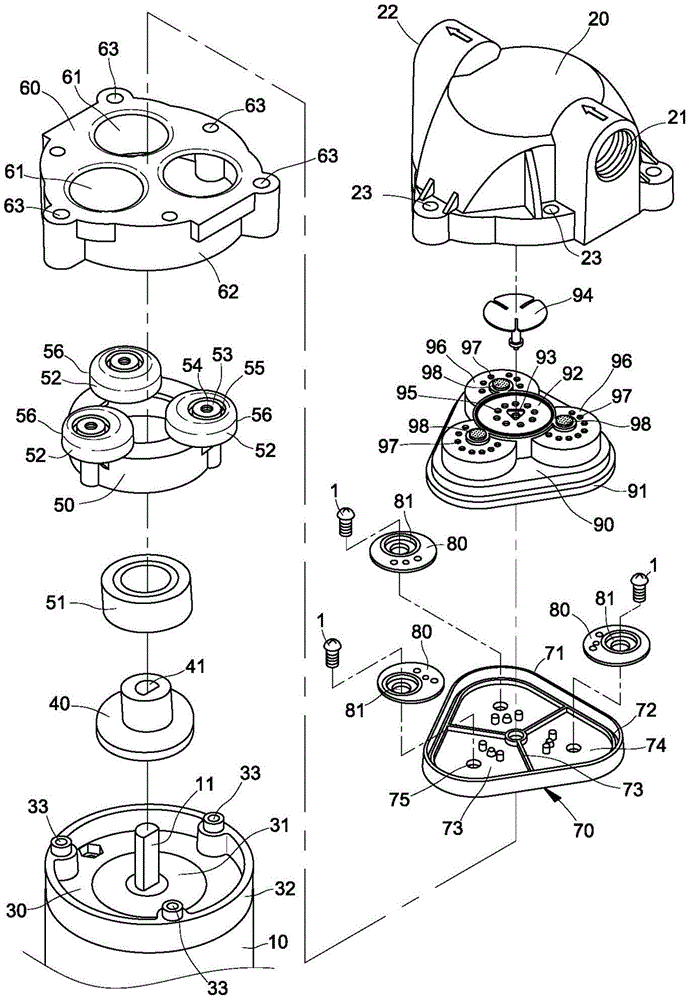
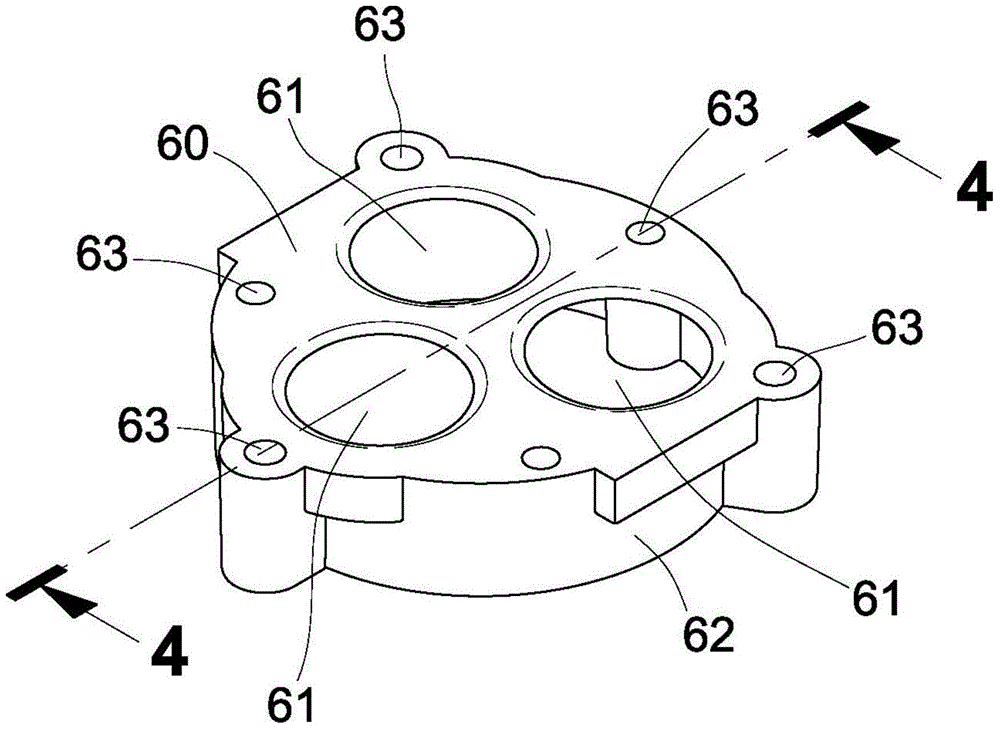
[0142] Such as Figure 15 to Figure 22 As shown, it is the first embodiment of the shock absorbing structure of the diaphragm booster pump of the present invention, which is an arc-shaped groove 65 that is recessed downward around the periphery of each actuation hole 61 on the top surface of the pump head seat 60 , and on the bottom surface of the diaphragm 70 corresponding to the position of each arc-shaped groove 65, an arc-shaped protrusion 77 is protruded downward, so that after the bottom surface of the diaphragm 70 and the top surface of the pump head seat 60 are attached to each other, The three arc-shaped protrusions 77 on the bottom surface of the diaphragm 70 are completely embedded in the three arc-shaped grooves 65 on the top surface of the pump head seat 60, and are positioned between the arc-shaped protrusions 77 on the bottom surface of the diaphragm 70 and the positioning convex ring block 76. form a shorter moment arm length L2 (such as Figure 22 shown in th...


PUM


Abstract

The invention relates to a shock absorption structure of a diaphragm booster pump. According to the shock absorption structure, an arc-shaped groove is downwardly and concavely formed in the position, on the periphery of each actuation perforation hole, of the top surface of a pump head base in the diaphragm booster pump, an arc-shaped bump is downwardly and convexly arranged at the position, corresponding to each arc-shaped groove, of the bottom surface of a diaphragm, and after the bottom surface of the diaphragm is attached to the top surface of the pump head base, each arc-shaped bump of the bottom surface of the diaphragm is completely embedded in the corresponding arc-shaped groove of the top surface of the pump head base. Small moment arm length is achieved between the arc-shaped bumps of the bottom surface of the diaphragm and a positioning convex ring, so that the torque generated by multiplying acting force obtained when wobblers push the bottom surface of the diaphragm upwards by the small moment arm length becomes small, and the strength of shock generated when the diaphragm booster pump is actuated is substantially reduced.

Description

technical field [0001] The present invention is related to a diaphragm booster pump installed in a reverse osmosis purification, in particular to a structure that can greatly reduce the vibration intensity of the pump body when it is actuated, so that it can be installed in a reverse osmosis water filter After the case is on, it will not resonate with the case and cause annoying sounds. Background technique [0002] Currently known diaphragm booster pumps used in reverse osmosis water filters have been disclosed such as U.S. Patent Nos. No. 6840745 and No. 6892624 are both, and its structure is as follows Figure 1 to Figure 9 Shown, by a motor 10, a motor front cover 30, an inclined eccentric cam 40, a balance wheel seat 50, a pump head seat 60, a diaphragm 70, three piston push blocks 80, a piston valve body 90 and a The pump head cover 20 is combined; wherein, a bearing 31 is embedded in the center of the motor front cover 30, which is penetrated by the output shaft 11 o...

Claims


Application Information

Patent Timeline
Patent Type & Authority Applications(China)
IPC IPC(8): F04B43/04F04B53/00
CPCF04B43/0045F04B43/0054F04B43/04F04B53/001F04B43/14F04B43/02F04B53/16F04B53/14F04B53/10F05B2260/96F05B2280/4003F05B2210/11
Inventor 蔡应麟徐兆火
Owner FOSHAN CITY SANJIAOZHOU ELECTRICAL TECH CO LTD
Why Eureka
Try Eureka