Novel multistage centrifugal pump

A centrifugal pump, a new type of technology, applied in the direction of pumps, pump components, non-variable pumps, etc., can solve the problems of easy formation of air binding, poor sealing performance of multi-stage centrifugal pumps, low output efficiency, etc., to ensure the sealing performance , Reduce gas entry and liquid leakage, and prevent deformation

Active Publication Date: 2015-07-22
JIANGSU JIANGYUAN MASCH CO LTD
View PDF8 Cites 2 Cited by
  • Summary
  • Abstract
  • Description
  • Claims
  • Application Information

AI Technical Summary

Problems solved by technology

[0007] Specifically, the technical problem to be solved by the present invention is to provide a new type of multistage centrifugal pump to solve the technical problems of current multistage centrifugal pumps such as poor sealing performance, easy formation of air locks, and low output efficiency.

Method used


Image

  • Novel multistage centrifugal pump
  • Novel multistage centrifugal pump
  • Novel multistage centrifugal pump

Examples


Embodiment 1

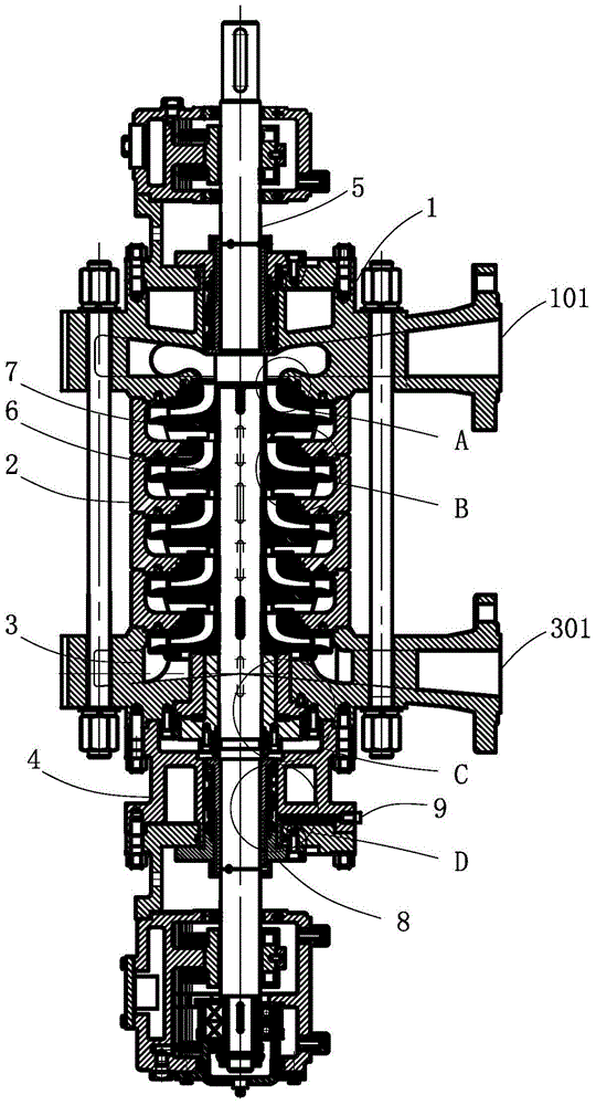
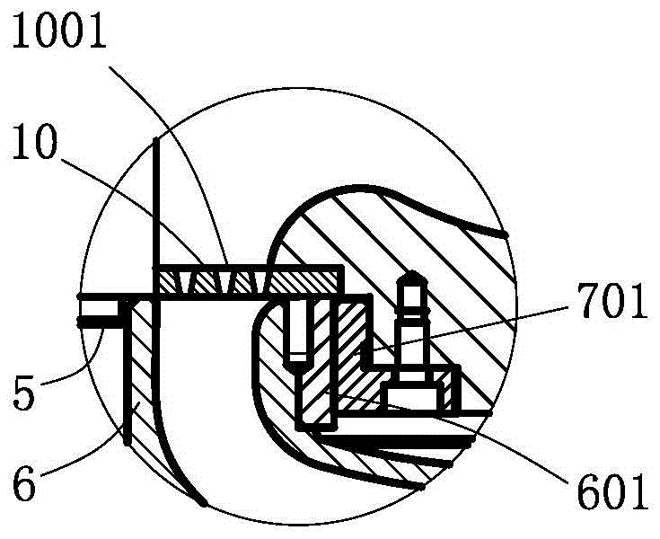
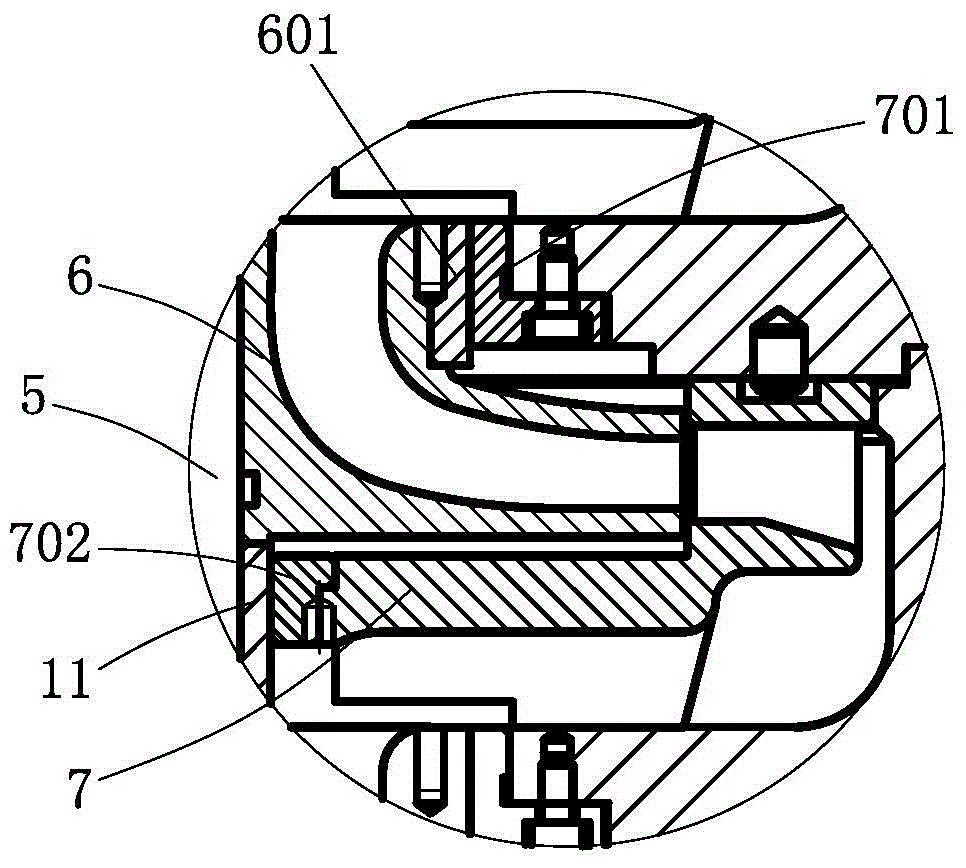
[0034] Such as figure 1 , figure 2 , image 3 , Figure 4 and Figure 5Commonly shown, the present invention provides a multi-stage centrifugal pump, including a pump body, in which a drive shaft 5 is rotatably installed, and the pump body includes a suction section 1, a middle section 2 and a discharge section 3, and the middle section 2 is arranged on the suction section 1 Between the discharge section 3, the suction section 1 is provided with a suction port 101, and the discharge section 3 is provided with a discharge port 301. A number of impellers 6 are fixedly installed on the transmission shaft 5 located in the middle section 2, and the middle section 2 is provided with corresponding impellers 6. The guide vane 7 is provided with a suction sealing mechanism between the suction section 1 and the transmission shaft 5. Because it is negative pressure suction, the sealing mechanism of the suction section 1 can choose commonly used methods such as labyrinth seals and mec...

Embodiment 2

[0043] Such as Figure 6 shown, and refer to Figure 2 to Figure 5 , the present invention provides a multi-stage centrifugal pump, the structure of which is basically the same as that of Embodiment 1, the difference is that the pressure compensation channel 21 is not provided with a thrust rod 20, but the pressure compensation channel 21 is directly connected to the spout through a pipeline 28 The outlet 301 naturally balances the pressure on both sides of the sealing gasket 26 through the liquid pressure of the outlet 301, and automatically adjusts with the pressure change of the outlet 301, which is more convenient and accurate than using the thrust rod 20 to adjust.


PUM


Abstract

The invention discloses a novel multistage centrifugal pump, and belongs to the technical field of fluid pumps. The centrifugal pump comprises a pump body, and the pump body is internally provided with a transmission shaft in a rotating mode. The pump body comprises an intake segment, a middle segment and an output segment, and the middle segment is arranged between the intake segment and the output segment. The transmission shaft is fixedly provided with a plurality of impellers, and the middle segment is provided with guide vanes corresponding to the impellers. An intake sealing mechanism is arranged between the intake segment and the transmission shaft, and an output sealing mechanism is arranged between the output segment and the transmission shaft. An air filter plate is arranged between the intake segment and the first-stage impeller. The air filter plate is fixedly arranged on the pump body and provided with a plurality of through holes. The output segment is fixedly connected with a compensation shell. The transmission shaft penetrates out of the compensation shell. A compensation sealing mechanism for preventing liquid from leaking is arranged between the compensation shell and the transmission shell. By means of the novel multistage centrifugal pump, the technical problems that an existing multistage centrifugal pump is poor in sealing performance and low in output efficiency, and air bind is formed easily are solved, and the novel multistage centrifugal pump is widely applied to continuous conveying of fluid.

Description

technical field [0001] The invention relates to a pump, more particularly to a novel multistage centrifugal pump, which belongs to the technical field of fluid pumps. Background technique [0002] The centrifugal pump works by rotating the impeller to cause the water to undergo centrifugal motion. Its working principle is: when the liquid enters the pump casing, due to the gradual expansion of the flow channel in the volute-shaped pump casing, the flow rate of the liquid gradually decreases, and a part of the kinetic energy is transformed into Static pressure energy, so the liquid flows out along the discharge port at a higher pressure. At the same time, a certain vacuum is formed at the center of the impeller due to the liquid being thrown out, and the pressure Pa at the liquid surface is higher than that at the center of the impeller. Therefore, the liquid in the suction line enters the pump under the action of the pressure difference, the impeller rotates continuously, a...

Claims


Application Information

Patent Timeline
Patent Type & Authority Applications(China)
IPC IPC(8): F04D1/06F04D29/08F04D29/66F04D29/00
Inventor 张妍杨海霞
Owner JIANGSU JIANGYUAN MASCH CO LTD
Why Eureka
Try Eureka