Condensate water air drying type top-mounted compression, condensation and evaporation integrated type refrigerator structure

A technology of condensing, evaporating and evaporating boxes, which is applied in the refrigeration industry, in the structural field of condensed water self-drying type upward compression condensing and evaporating integrated refrigerators, which can solve the problems of flowing, rusted equipment parts, complex structures, etc., and achieve the problem of dripping water, The effect of easy maintenance and simple assembly process

Inactive Publication Date: 2015-07-22
YINDU KITCHEN EQUIP
View PDF6 Cites 6 Cited by
  • Summary
  • Abstract
  • Description
  • Claims
  • Application Information

AI Technical Summary

Problems solved by technology

[0002] At present, in the structure of the refrigerator between the top units, the defrosting condensed water of the evaporator is generally discharged straight down or backward into the water tray on the back of the cabinet. Complicated, the overall structure cannot be achieved, and the condensed water will flow inside and outside the machine, polluting and corroding equipment parts
After searching by the applicant, no effective means to solve the above problems have been found

Method used


Image

  • Condensate water air drying type top-mounted compression, condensation and evaporation integrated type refrigerator structure
  • Condensate water air drying type top-mounted compression, condensation and evaporation integrated type refrigerator structure
  • Condensate water air drying type top-mounted compression, condensation and evaporation integrated type refrigerator structure

Examples


Embodiment Construction

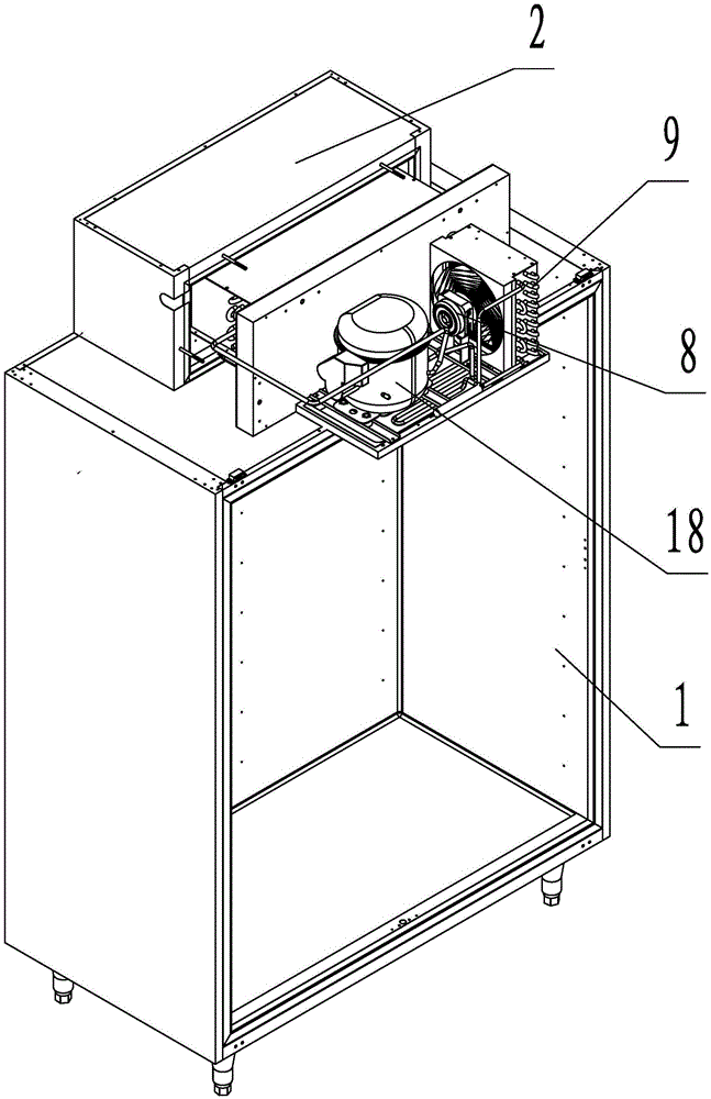
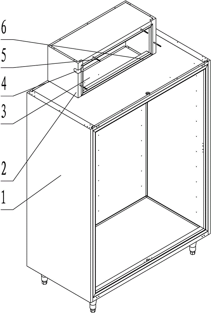
[0016] Such as figure 1 , figure 2 , Figure 5 As shown, the condensed water self-drying top-mounted compression condensation evaporation integral type refrigerator in this embodiment is composed of a cabinet and a refrigeration system. The cabinet is formed by integral foaming of the upper evaporation box 2 and the lower storage box 1. The evaporation box 2 and the storage box 1 have a through hole 3 for air circulation. The evaporating box 2 is equipped with an evaporating box cover 17, and the refrigeration system is respectively installed on the inner and outer sides of the evaporating box cover 17.

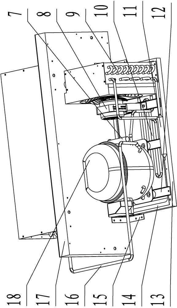
[0017] Such as image 3 As shown, the outside of the evaporator cover 17 is installed with a machine base plate 13 through a right-angled connecting bracket 15, and an evaporating pan 14 is installed on the machine base plate, and a shelf 12 is set on the evaporating pan. The heavier compressor 18, Condenser 9 and condensing fan 8 are all installed on the shelves. The c...


PUM


Abstract

The invention relates to a condensate water air drying type top-mounted compression, condensation and evaporation integrated type refrigerator structure. The integrated type refrigerator structure aims to achieve the purposes of solving the outlet problem of condensate water, simplifying the product structure and bringing convenience to installation and overhaul. According to the technical scheme, the structure is composed of a box and refrigeration systems, and the box is formed by integrally foaming of an upper evaporation box provided with an evaporation box cover and a lower storage box. The refrigeration systems are installed at the inner side and the outer side of the evaporation box cover respectively, a compressor, an evaporating dish, a high-pressure exhaust pipe, a condenser and a condensation draught fan are distributed at the outer side of the evaporation box cover, a pipe end of a high-pressure exhaust coiled pipe is arranged in the evaporating dish, the other end of the high-pressure exhaust coiled pipe is connected with the condenser, and the condensation draught fan is installed between the condenser and the compressor. An evaporator, an evaporation draught fan, an evaporator water pan and a drainage pipe are arranged at the inner side of the evaporation box cover, the evaporator is installed in the evaporation box, the evaporation draught fan is installed below an evaporation draught fan support, the evaporator water pan is installed underneath the evaporator, one end of the drainage pipe is connected to the evaporator water pan, and the other end of the drainage pipe is suspended above the evaporating dish.

Description

technical field [0001] The invention relates to refrigeration equipment, in particular to a condensed water self-drying overhead compression condensing and evaporating integrated refrigerator structure. Suitable for refrigeration industry. Background technique [0002] At present, in the structure of the refrigerator between the top units, the defrosting condensed water of the evaporator is generally discharged straight down or backward into the water tray on the back of the cabinet. Complicated, the overall structure cannot be achieved, and the condensed water will flow inside and outside the machine, polluting and rusting equipment parts. After searching by the applicant, no effective means to solve the above problems has been found. Contents of the invention [0003] The technical problem to be solved by the present invention is to provide a condensed water self-drying top-mounted compression condensing and evaporating integrated refrigerator structure in view of the ...

Claims


Application Information

Patent Timeline
IPC IPC(8): F25D11/00F25D19/00F25D21/14
CPCF25D11/00F25D19/003F25D21/14F25D2321/141
Inventor 叶进蒋小林张惠影
Owner YINDU KITCHEN EQUIP
Why Eureka
Try Eureka