Phase-change energy storage box

A technology of phase change energy storage and solid-liquid phase change, which is applied in the field of heat exchange, can solve the problems of low heat exchange effect of heat exchanger, unstable water supply temperature, and large water tank volume, so as to facilitate assembly production and ensure continuous Constant temperature operation, simple and convenient installation

Inactive Publication Date: 2015-07-22
TIANJIN UNIV OF COMMERCE
View PDF17 Cites 3 Cited by
  • Summary
  • Abstract
  • Description
  • Claims
  • Application Information

AI Technical Summary

Problems solved by technology

[0004] Because the heat transfer effect of the heat exchanger is relatively low, the volume of the general water tank is relatively large
At the same time, because the heat transfer of the heat exchanger is affected by the heat source, it often causes the instability of the water supply temperature and affects the use

Method used


Image

  • Phase-change energy storage box
  • Phase-change energy storage box

Examples


Embodiment 1

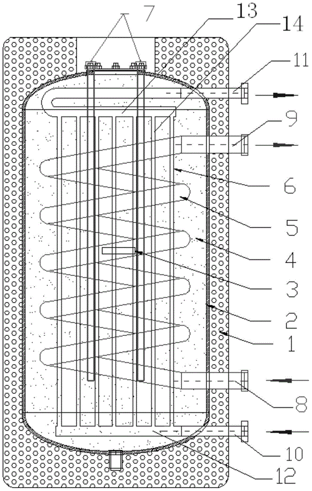
[0024] The schematic diagram of the phase change energy storage tank using copper heat exchange coil as the heat medium heat exchanger in the present invention is as follows figure 1 As shown, it includes a box body 2, a refrigerant heat exchanger 6, a heat medium heat exchanger 5, and an electric auxiliary heater 7. In order to ensure the strength of the box body, the box body 2 is made of steel. The compartment 2 is filled with a solid-liquid phase change energy storage material 4, and an insulation layer 1 is installed outside the compartment 2. The insulation layer 1 can use various insulation materials. The insulation layer in this embodiment is polyurethane foam layer. The refrigerant heat exchanger 6 , heat medium heat exchanger 5 and electric auxiliary heater 7 are placed in the solid-liquid phase change energy storage material 4 inside the box body 2 . The car body 2 is provided with maintenance holes. The refrigerant inlet of the refrigerant heat exchanger 6 is con...

Embodiment 2

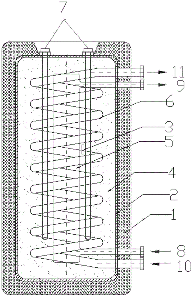
[0029] The schematic diagram of the phase change energy storage tank using copper heat exchange coil as the refrigerant heat exchanger in the present invention is as follows figure 2 As shown, it includes a box body 2, a refrigerant heat exchanger 6, a heat medium heat exchanger 5, and an electric auxiliary heater 7. In order to ensure the strength of the box body, the box body 2 is made of steel. The compartment 2 is filled with a solid-liquid phase change energy storage material 4, and an insulation layer 1 is installed outside the compartment 2. The insulation layer 1 can use various insulation materials. The insulation layer in this embodiment is polyurethane foam layer. The refrigerant heat exchanger 6 , heat medium heat exchanger 5 and electric auxiliary heater 7 are placed in the solid-liquid phase change energy storage material 4 inside the box body 2 . The car body 2 is provided with maintenance holes. The refrigerant inlet of the refrigerant heat exchanger 6 is co...


PUM


Abstract

The invention discloses a phase-change energy storage box. Heat is absorbed through phase change of energy storage materials and is accumulated in the phase-change materials, the phase-change energy storage box becomes a heat preservation box, and a guarantee is provided for a user for using heat at any time. The phase-change energy storage box comprises a box body, a refrigerant heat exchanger, a heating medium heat exchanger and an electric auxiliary heater. The box body is internally filled with the solid-liquid phase-changer energy storage materials, a heat preserving layer is installed outside the box body, and the refrigerant heat exchanger, the heating medium heat exchanger and the electric auxiliary heater are arranged in the solid-liquid phase-change energy storage materials in the box body; the box body is provided with a maintenance hole; a refrigerant inlet of the refrigerant heat exchanger is connected with a refrigerant inlet connecting pipe penetrating through the box body and the heat preserving layer, and a refrigerant outlet of the refrigerant heat exchanger is connected with a refrigerant outlet connecting pipe penetrating through the box body and the heat preserving layer; a heating medium inlet of the heating medium heat exchanger is connected with a heating medium inlet connecting pipe penetrating through the box body and the heat preserving layer, and a heating medium outlet of the heating medium heat exchanger is connected with a heating medium outlet connecting pipe penetrating through the box body and the heat preserving layer.

Description

technical field [0001] The invention relates to the technical field of heat exchange, in particular to a phase change energy storage box for storing energy through phase change materials. Background technique [0002] With the continuous improvement of people's living standards, people's demand for domestic hot water is also increasing. People hope that when they want to use hot water, they can use it directly without waiting, and at the same time require to ensure its quality and constant temperature water supply. [0003] Most of the current hot water supply systems adopt a structural design in which a heat exchanger is installed in a water tank. The water in the water tank is heated by a heat exchanger, and then supplied to users. [0004] Because the heat exchange effect of the heat exchanger is relatively low, the volume of the general water tank is relatively large. At the same time, because the heat transfer of the heat exchanger is affected by the heat source, it o...

Claims


Application Information

Patent Timeline
IPC IPC(8): F28D20/02F24H7/02
CPCY02E60/14
Inventor 邹同华邹国文
Owner TIANJIN UNIV OF COMMERCE
Why Eureka
Try Eureka