Stereo microscope with coaxial lighting effect

A technology for stereo microscopes and lighting effects, applied in the field of stereo microscopes, can solve the problems of affecting the operating space of stereo microscopes, high manufacturing costs, and easy loss, and achieve the effects of increasing operating space, low manufacturing costs, and improving utilization

Inactive Publication Date: 2015-07-22
MOTIC CHINA GRP CO LTD
View PDF31 Cites 4 Cited by
  • Summary
  • Abstract
  • Description
  • Claims
  • Application Information

AI Technical Summary

Problems solved by technology

[0003] In the sample observed by a stereo microscope, when the surface of the sample is highly reflective, it is difficult to achieve a clear observation of the sample with the existing ring lighting, oblique lighting, and double fiber lighting, so it is necessary to use coaxial lighting. Observed
[0004] On January 16, 2013, the applicant disclosed an invention patent with publication number CN202676975U and titled "A Stereo Microscope LED Coaxial Illumination Device". It is composed of mirror, lighting lens, corresponding electrical components, upper and lower substrate shells and connecting parts. When in use, you only need to install the device at the front end of the imaging objective lens of the stereo microscope, and you can get coaxial lighting observation effect with uniform brightness, but This coaxial lighting device is arranged at the front end of the imaging objective lens of the stereo microscope, which affects the compactness of the structure of the stereo microscope, complicates the structure of the stereo microscope, and is easy to lose as an independent accessory; secondly, the device needs The two LED lamp groups have low light energy utilization and high manufacturing cost; in addition, the device is installed at the front end of the imaging objective lens of the stereo microscope, which will also affect the operating space of the stereo microscope, making it impossible to add additional objective lenses or Other functional accessories

Method used


Image

  • Stereo microscope with coaxial lighting effect
  • Stereo microscope with coaxial lighting effect
  • Stereo microscope with coaxial lighting effect

Examples


Embodiment Construction

[0024] The present invention will be described in further detail below in conjunction with the accompanying drawings and specific embodiments.

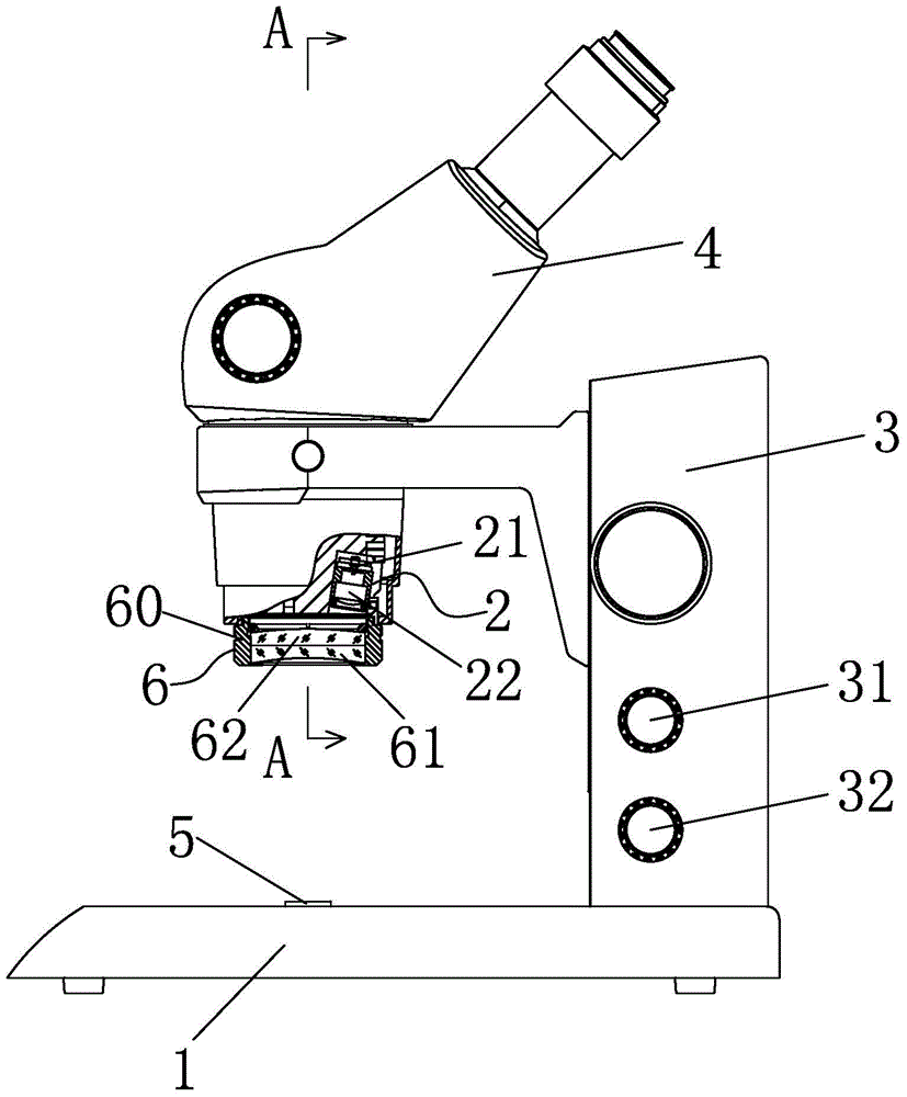
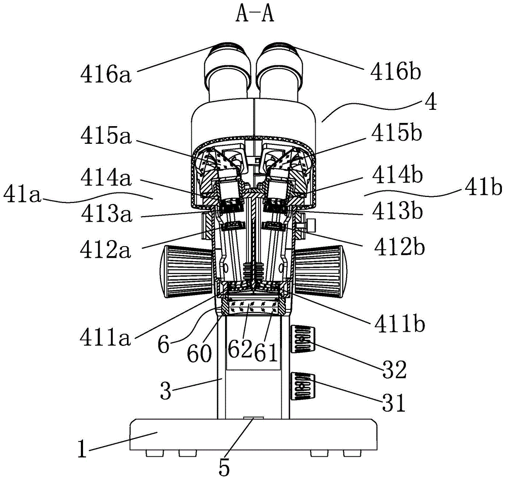
[0025] like Figure 1 to Figure 4 As shown, a stereomicroscope with coaxial lighting effects includes a base 1, an illumination source 2, a column 3 fixed on the base 1, and a microscope main body 4 connected to the column 3, and the microscope main body 4 includes left-right symmetrical There are two optical imaging systems, the two optical imaging systems are the left optical imaging system 41a and the right optical imaging system 41b.

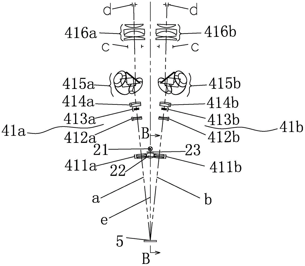
[0026] The left optical imaging system 41a is provided in sequence from bottom to top: a fixed front group 411a, a lower zoom group 412a, an upper zoom group 413a, a rear fixed group 414a, and a mirror group 415a is also arranged on the rear fixed group 414a. and eyepiece 416a';

[0027] The right optical imaging system 41b includes from bottom to top: a fixed front group 411b, a lower zoom group ...


PUM


Abstract

The invention discloses a stereo microscope with coaxial lighting effect. The stereo microscope comprises a base, a lighting source, a column fixed on the base and a microscope body connected on the column. The microscope body comprises two zygomorphic optical imaging systems, the optical axis of the left optical imaging system is a first optical axis, the optical axis of the right optical imaging system is a second optical axis, the optical axis of the lighting source is a third optical axis, the lighting source is arranged inside the microscope body, the lighting source comprises an LED lamp and an illuminating lens under the LED lamp; the first optical axis and the second optical axis intersect at the same point on the surface of a specimen, the third optical axis is on the symmetry plane of the first optical axis and the second optical axis; furthermore, the third optical axis intersects with the first optical axis and the second optical axis at the same point on the surface of the specimen. The stereo microscope has the effect of coaxial lighting, is compact in structure, low in manufacturing cost, particularly suitable for deep hole observation and the checking of teeth.

Description

technical field [0001] The invention relates to a stereo microscope, in particular to a stereo microscope with coaxial lighting effect. Background technique [0002] Stereo microscope is also called "solid microscope" or "stereo microscope". [0003] In the sample observed by a stereo microscope, when the surface of the sample is highly reflective, it is difficult to achieve a clear observation of the sample with the existing ring lighting, oblique lighting, and double fiber lighting, so it is necessary to use coaxial lighting. Observed. [0004] On January 16, 2013, the applicant disclosed an invention patent with publication number CN202676975U and titled "A Stereo Microscope LED Coaxial Illumination Device". It is composed of mirror, lighting lens, corresponding electrical components, upper and lower substrate shells and connecting parts. When in use, you only need to install the device at the front end of the imaging objective lens of the stereo microscope, and you can...

Claims


Application Information

Patent Timeline
Patent Type & Authority Applications(China)
IPC IPC(8): G02B21/06G02B21/22
CPCG02B21/06G02B21/22
Inventor 夏波江育英
Owner MOTIC CHINA GRP CO LTD
Why Eureka
Try Eureka