A new method of manufacturing wire-wound inductors

A production method and technology of inductance, which is applied in the field of inductance, can solve the problems of power capacity and rated current that cannot meet the requirements of use, easy damage of winding and pin connections, poor performance indicators of color-coded inductance, etc., so as to facilitate installation into the circuit On the board, avoid winding displacement, the effect of large inductance

Active Publication Date: 2017-02-22
GUANGDONG KUANPU TECH CO LTD
View PDF6 Cites 0 Cited by
  • Summary
  • Abstract
  • Description
  • Claims
  • Application Information

AI Technical Summary

Problems solved by technology

However, due to the large range of ambient temperature, the ambient temperature is generally -55°C to +70°C; in high-temperature and low-temperature environments, the performance indicators of color-coded inductors are poor, and the power capability and rated current cannot meet the use requirements. Self-resonance The frequency is low; after the high and low temperature impact test, the color code inductance has plastic discoloration and burnout, etc.
Therefore, the current inductor needs to increase the inductance and increase the winding length, but the current inductor skeleton winding space is insufficient. For small-volume products, the inductor volume is strictly limited, and the inductance cannot be increased simply by directly increasing the inductor size.
In addition, the existing inductors still have disadvantages such as poor mechanical strength, easy damage to the winding and pin connections, easy loosening of the winding and not being close to the skeleton, inconvenient processing and low production efficiency, etc.

Method used


Image

  • A new method of manufacturing wire-wound inductors
  • A new method of manufacturing wire-wound inductors
  • A new method of manufacturing wire-wound inductors

Examples


Embodiment 1

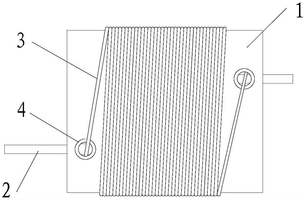
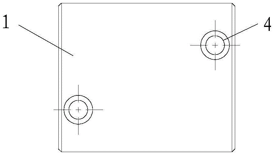
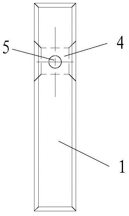
[0039] In this embodiment, the wire wound inductor has a structure such as figure 1 Shown; Inductor includes skeleton 1, winding 3 and two pins 2. Skeleton 1 is flat. figure 2 is a schematic diagram of the structure observed from the main view plane; image 3 It is a schematic diagram of the skeleton viewed from the right side. There are two wiring holes 4 on the front of the framework 1, and pin holes 5 are respectively opened on the two sides of the framework 1; each pin hole 5 communicates with the wiring hole 4 respectively; The connection between 5 and wiring hole 4 extends to the outside of frame 1 along pin hole 5 .

[0040] The winding 3 includes a main body and two positioning parts; the main body is wound on the skeleton 1; one end of the two positioning parts is respectively connected to the main body, and the other ends of the two positioning parts respectively extend into the wiring holes 4 to connect with the lead wires. The pins 2 are wound to form a conducti...

Embodiment 2

[0045] The wire-wound inductor in this embodiment includes a skeleton, a winding wire and two pins; the skeleton is flat; two wiring holes and two pin holes are provided on the skeleton; each pin hole is connected to the wiring hole; Each pin extends from the connection between the pin hole and the wiring hole to the outside of the skeleton along the pin hole; the winding is wound on the skeleton, and the two ends of the winding are respectively extended into the wiring hole to connect with the pins to form a conductive structure.

[0046] The frame of the inductor in this embodiment is flat, with less material and high mechanical strength, which can provide a larger winding space; compared with the traditional inductor, the inductor winding of this embodiment is wound along the flat frame, and the winding length Longer, it is beneficial to make an inductor with a large inductance; the skeleton is provided with wiring holes and pin holes for fixing the winding and pins, which ...

Embodiment 3

[0048] The structure of the inductor in this embodiment is as follows Figure 4 As shown, the difference from the first embodiment is that the frame 1 is provided with a positioning slot 1 6 and a positioning slot 2 7 communicating with the wiring hole 4 . The other ends of the two positioning parts of the winding wire 3 respectively extend into the wire routing hole 4 through the positioning groove one 6 to be wound with the pin 2 . The positioning groove 16 can effectively fix the position of the winding wire 3, so that the winding wire 3 is tightly wound, avoiding looseness, and improving the mechanical strength of the inductor; at the same time, it is convenient for processing.

[0049] The winding 3 also includes two reinforcing parts; one end of the two reinforcing parts is respectively connected to the other end of the two positioning parts, and the other ends of the two reinforcing parts extend to the outside of the skeleton 1 along the positioning groove 7 and are wou...


PUM

PropertyMeasurementUnit
diameteraaaaaaaaaa

Abstract

The invention provides a novel wire wound inductor. The novel wire wound inductor is characterized by comprising a bobbin, a wound wire and pins. The bobbin is in a flat shape. Wiring holes and pin holes are formed in the bobbin. The pin holes are communicated with the wiring holes. One end of each pin is arranged in the corresponding wiring hole, and the other end of each pin extends out of the bobbin through the corresponding pin hole. The wound wire comprises a body part and two positioning parts. The body part is wound around the bobbin. One end of each of the two positioning parts is connected with the body part, and the other ends of the two positioning parts extend into the wiring holes respectively and are twined with the pins, so a conductive structure is formed. The novel wire wound inductor is simple in structure, high in mechanical strength, large in wire winding space, convenient to machine and small in occupied space; besides, connection between the wound wire and the pins is firm. The invention further provides a manufacturing method of the novel wire wound inductor which is convenient to machine and capable of improving working efficiency, reducing the production cost and enhancing the fastness degree of connection between the wound wire and the pins.

Description

technical field [0001] The invention relates to the technical field of inductors, and more specifically, to a wire-wound inductor and a manufacturing method thereof. Background technique [0002] Inductors have functions such as filtering, oscillation, delay, and trapping, and are widely used in electronic circuits. For example, in an RF filter feed circuit, an inductor must be used to power a diode. At present, inductors generally include color ring inductors, color code inductors, magnetic core inductors, and air core inductors. [0003] Some products have higher requirements on inductance performance, such as radio frequency products, etc.; color-coded inductors are generally used in radio frequency filter feed circuits at present. However, due to the large range of ambient temperature, the ambient temperature is generally -55°C to +70°C; in high-temperature and low-temperature environments, the performance indicators of color-coded inductors are poor, and the power cap...

Claims


Application Information

Patent Timeline
Patent Type & Authority Patents(China)
IPC IPC(8): H01F27/30H01F41/04H01F41/06H01F41/076
Inventor 文俊
Owner GUANGDONG KUANPU TECH CO LTD
Why Eureka
Try Eureka