Die-casting die

A technology of die-casting molds and beams, which is applied in the field of aluminum alloy die-casting mold structures, can solve problems such as product bending deformation, bending deformation, and difficulty in simultaneously forming lateral forming holes and radial blind holes on the inner wall of the lateral forming holes, etc., to achieve Avoid the effect of bending deformation

Active Publication Date: 2015-07-29
NINGBO BEILUN HUASHENG MOLD FACTORY
View PDF8 Cites 5 Cited by
  • Summary
  • Abstract
  • Description
  • Claims
  • Application Information

AI Technical Summary

Problems solved by technology

[0003] One purpose of the present invention is to solve the problem that the existing aluminum alloy die-casting mold is prone to product package upper mold and bending deformation when forming products with openings on both sides of the upper and lower sides, and to provide a method that can ensure that all products stay in the lower mold during molding. Die-casting mold, so as to effectively avoid bending deformation of the formed product
[0004] Another object of the present invention i...

Method used


Image

  • Die-casting die
  • Die-casting die
  • Die-casting die

Examples


Embodiment Construction

[0021] The present invention will be further described below in conjunction with the accompanying drawings and specific embodiments.

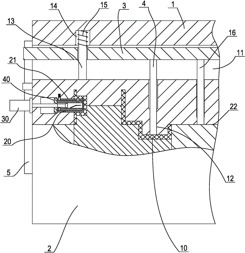
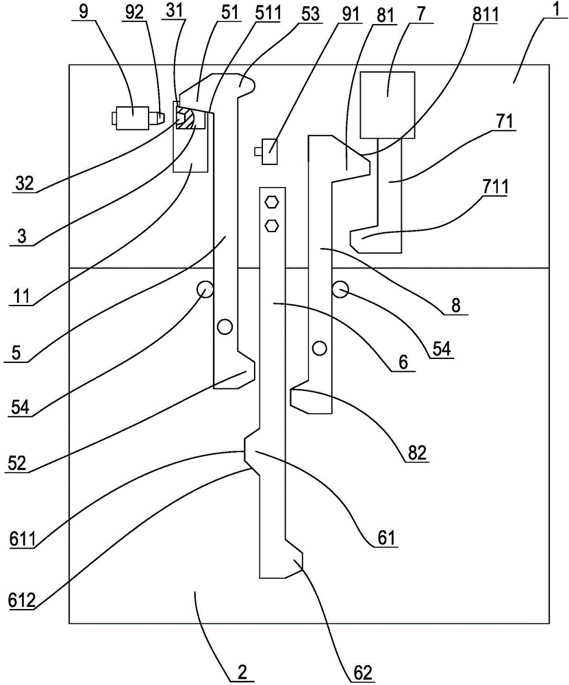
[0022] like figure 1 , figure 2 As shown, a die-casting mold is suitable for products with openings or cavities facing the upper and lower sides at the same time, or products with relatively close molding forces on the upper and lower sides of the parting surface, specifically including products with a pouring system Upper die 1, lower die 2 with ejection mechanism. For the sake of explanation, we refer to the mold splitting and mold closing directions of the upper and lower molds as the longitudinal direction of the die-casting mold, and correspondingly, the direction perpendicular to the longitudinal direction is called the transverse direction of the die-casting mold. Firstly, a long groove 11 arranged horizontally through the left and right sides is set in the upper mold. The cross section of the long groove is rectangular. The guide ho...


PUM


Abstract

The invention discloses a die-casting die which comprises an upper die and a lower die. Elongated slots penetrating the left side and the right side of the upper die are formed in the upper die, a beam is movably arranged in the elongated slots, a counter pull rod extending to a cavity of the upper die is arranged on the beam, beam pressure springs abutted to the beam are arranged on the upper sides of the elongated slots, first pull hooks and corresponding limit structures are rotatably arranged on the left side and the right side of the lower die respectively, hook portions are arranged at the upper ends of the first pull hooks, first projections extending to the other side are arranged at the lower ends of the first pull hooks, the hook portions hook ends of the beam extending out of the upper die, torsion springs pinning the first pull hooks are arranged on rotating shafts of the first pull hooks, a poke rod is fixedly arranged on the upper die and beside the first projections of the first pull hooks, a projecting first push block is arranged on the lower portion of the poke rod and close to the first projections, and guide inclined surfaces are arranged at two ends of the first push block. All products can stay on the lower die in forming, so that bending deformation of the formed products is effectively avoided.

Description

technical field [0001] The invention relates to the technical field of molds, in particular to an aluminum alloy die-casting mold structure. Background technique [0002] Existing aluminum alloy die-casting molds usually include an upper mold, a lower mold, a pouring system arranged on the upper mold, an ejection mechanism arranged on the lower mold, and a cooling system, etc. As far as the product with cavity is concerned, in order to facilitate the ejection of the product after molding, a concave cavity is usually set on the upper mold, and a convex core is set on the lower mold. When the upper and lower molds are combined, the upper mold The cavity of the molded product is formed between the cavity body and the core of the lower mold. After the product is formed and cooled, the upper and lower molds are separated, and the product stays on the lower mold by the mold core force generated by its cooling shrinkage. Finally, the product is pushed along the mold through the ej...

Claims


Application Information

Patent Timeline
IPC IPC(8): B22D17/22
Inventor 陆卫国
Owner NINGBO BEILUN HUASHENG MOLD FACTORY
Why Eureka
Try Eureka