Pneumatic bench clamp

A vise and cylinder technology, applied in the field of pneumatic vise, can solve the problems of no protection, time-consuming and labor-intensive, easy to damage, etc.

Inactive Publication Date: 2015-07-29
SHENZHEN FSJ INTELLIGENT TECH CO LTD
View PDF6 Cites 9 Cited by
  • Summary
  • Abstract
  • Description
  • Claims
  • Application Information

AI Technical Summary

Problems solved by technology

[0004] Disadvantages of the existing technology: the traditional mechanical vise is bulky, inefficient, time-consuming and labor-intensive, and the spiral opening and closing is easy to be damaged without protection; the hydraulic vise can realize automatic control, but the cost is high, pollution is involved, and the maintenance is complicated

Method used


Image

  • Pneumatic bench clamp
  • Pneumatic bench clamp
  • Pneumatic bench clamp

Examples


Embodiment Construction

[0025] The present invention will be described in detail below in conjunction with specific embodiments.

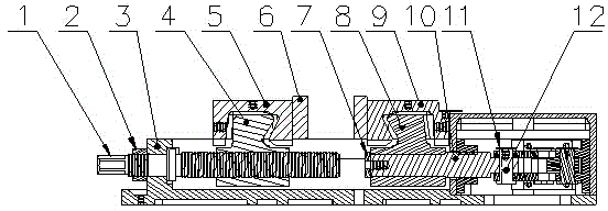
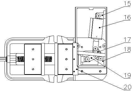
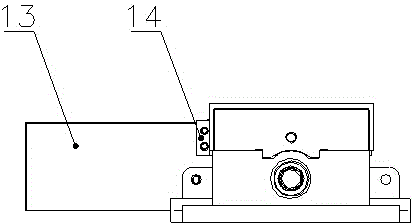
[0026] Such as figure 1 , 2, 3, 4, 5, 6, and 7, a pneumatic vise includes: a vise assembly mounting base 3 and a mechanism fixing base 18 perpendicular to the vise assembly mounting base, on which the mechanism fixing base 18 A cylinder fixing seat 15 is provided, and a cylinder assembly 16 is arranged on the cylinder fixing seat 15. The cylinder assembly 16 is connected to a dial block 17, and the dial block 17 is connected to a connecting piece 19, and the connecting piece 19 is connected to the The vise assembly is installed on the vise mechanism on the base 3, and the cylinder assembly drives the vise mechanism to reciprocate through the plectrum and the connecting piece to realize the opening and closing of the vise.

[0027] Further, a preferred structure is that the cylinder assembly 16 is a double-acting cylinder.

[0028] Further, the preferred structure is tha...


PUM


Abstract

The invention discloses a pneumatic bench clamp. The pneumatic bench clamp comprises a bench clamp assembly mounting base and a mechanism fixing seat which is perpendicular to the bench clamp assembly mounting base, wherein a cylinder fixing seat is arranged on the mechanism fixing seat; a cylinder assembly is mounted on the cylinder fixing seat; the cylinder assembly is connected to a stirring block; the stirring block is connected with a connecting piece; the connecting piece is connected to a bench clamp mechanism which is arranged on the bench clamp assembly mounting base; the cylinder assembly drives the bench clamp mechanism to move reciprocally through the stirring piece and the connecting piece so as to realize the opening and closing of the bench clamp. The pneumatic bench clamp is unique in structural design; the cylinder in the bench clamp is taken as a power source; the pressure of compressed air is converted into mechanical energy to drive the bench clamp to move reciprocally so as to realize the opening and the closing of the bench clamp; the space is saved through a non-threaded pushing structure; the opening and closing response action is fast; compared with a traditional mechanical bench clamp and a hydraulic bench clamp, the efficiency is obviously improved.

Description

technical field [0001] The invention relates to a pneumatic vise, which belongs to the field of mechanical processing. Background technique [0002] The vise is a commonly used auxiliary tool in the machining industry, and the rational use of the vise directly affects the quality and efficiency of machining. [0003] At present, there are traditional mechanical vise and hydraulic vise. [0004] Disadvantages of the existing technology: the traditional mechanical vise is heavy to use, inefficient, time-consuming and labor-intensive, and the spiral opening and closing is easy to be damaged without protection; the hydraulic vise can realize automatic control, but the cost is high, pollution is involved, and the maintenance is complicated. Contents of the invention [0005] In order to overcome the shortcomings of the existing traditional mechanical vise and hydraulic vise, the present invention provides a pneumatic vise powered by a cylinder, which ensures the stability ...

Claims


Application Information

Patent Timeline
Patent Type & Authority Applications(China)
IPC IPC(8): B23Q3/06B25B1/18B25B1/10
CPCB23Q3/066B25B1/10B25B1/18
Inventor 刘学洪
Owner SHENZHEN FSJ INTELLIGENT TECH CO LTD
Why Eureka
Try Eureka