Automatic mold oil spraying system for mold frame

A release oil and oil supply system technology, which is applied in the field of building material processing, can solve the problem of quality impact in the pouring, release, peeling and steaming of aerated concrete blocks, different atomization effects of release oil, and spraying Inconsistent thickness and other problems, to ensure the uniformity of spraying, reduce the difference in spraying distance, and achieve the effect of uniform spraying

Inactive Publication Date: 2015-07-29
GUIZHOU CHANGTAIYUAN ENERGY SAVING BUILDING MATERIALS CO LTD
View PDF6 Cites 8 Cited by
  • Summary
  • Abstract
  • Description
  • Claims
  • Application Information

AI Technical Summary

Problems solved by technology

[0005] 1. Waste of demoulding oil: At the beginning, the two spray guns work at the same time, and the traveling mechanism travels from left to right for spraying operations. During the walking process, the left spray gun will repeatedly spray the area sprayed by the right spray gun, resulting in demoulding oil waste;
[0006] 2. Uneven spraying: due to the angle between the arrangement of the spray gun and the horizontal plane, there is a spraying distance difference S (S=L2-L1) between the spraying distance L1 and L2 between the spraying point A and the spraying point B, and the spraying from the nozzle The speed of the release oil is the same, which leads to the difference in the atomization effect of the release oil at the two points A and B, and finally causes the spraying thickness of the two points A and B to be inconsistent. The result of the entire spraying is that the spraying thickness of each plane of the entire mold frame Inconsistencies and different spraying thicknesses in different areas within a single plane will have a quality impact on the pouring, stripping, peeling, and steaming processes of aerated concrete blocks

Method used


Image

  • Automatic mold oil spraying system for mold frame
  • Automatic mold oil spraying system for mold frame
  • Automatic mold oil spraying system for mold frame

Examples


Embodiment Construction

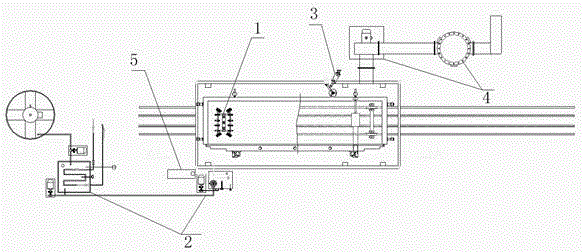
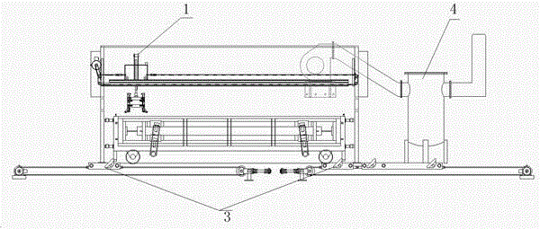
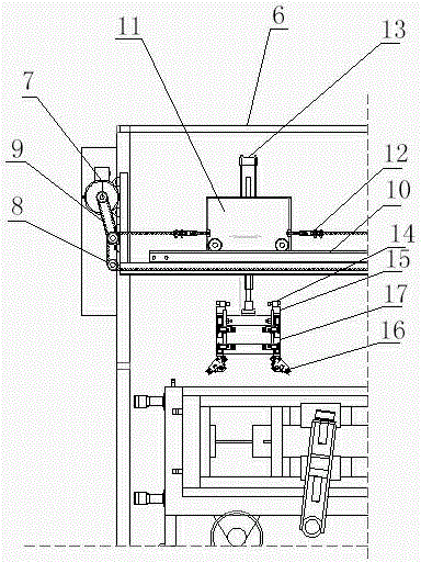
[0033] Below in conjunction with preferred embodiments, the mold frame release oil spraying system proposed according to the present invention, its specific implementation, structure, features and methods are described in detail below.

[0034] Such as Figure 1-3 As shown, the mold frame release oil spraying system of the present invention includes an oil injection system 1, an oil supply system 2, a mold frame positioning system 3, an exhaust purification system 4 and an electric control system 5, wherein: the oil injection system 1 is constructed by The traveling mechanism and the spraying mechanism on the main frame 6 of the fuel injection system are composed; the traveling mechanism includes a horizontal movement drive motor 7, a synchronous wheel 8 connected with the drive motor 7, a synchronous belt 9, a track 10 and a horizontal movement trolley 11, and the horizontal movement The trolley 11 is connected to the timing belt 9 through a timing belt connector 12; the spra...


PUM


Abstract

The invention discloses an automatic mold oil spraying system for a mold frame. The system comprises an oil spraying system (1), an oil supply system (2), a mold frame positioning system (3), an exhaust purification system (4) and an electric control system (5), wherein the oil spraying system (1) consists of a traveling mechanism erected on a main oil spraying system architecture (6) and a spraying mechanism; the traveling mechanism comprises a horizontal moving driving motor (7), a synchronizing wheel (8) connected with the driving motor (7), a synchronous belt (9), a rail (10) and a horizontal moving trolley (11); the horizontal moving trolley (11) is connected with the synchronous belt (9) through synchronous belt connectors (12); the spraying mechanism comprises a cylinder (13) and a sprayer connected onto the cylinder (13); the sprayer comprises CYL motion control electromagnetic valves (14) fixedly arranged on a bracket (17), valve terminals (15) and front, rear, left and right rows of spraying guns (16). The system has the characteristics of uniform spraying, high controllability, high efficiency and easiness in popularization.

Description

technical field [0001] The invention relates to the technical field of building material processing, in particular to an automatic spraying system for mold frame release oil. Background technique [0002] Air-entrained concrete block is a new type of building material that is lightweight, porous, thermal insulation, good fire resistance, nailable, sawable, planable, and has certain earthquake resistance. [0003] In the production process of air-entrained concrete blocks, it is necessary to apply release oil to the surface of the formwork before the pouring process. Aiming at the problem of brushing the release oil on the mold frame, the current manual brushing is labor-intensive and time-consuming, and the temperature inside the mold frame is high, the working environment is poor, the labor intensity is high, and the efficiency is low. In the process of manual brushing, the amount and temperature of release oil cannot be quantitatively controlled, and problems such as un...

Claims


Application Information

Patent Timeline
Patent Type & Authority Applications(China)
IPC IPC(8): B28B7/38
CPCB28B7/382B28B7/388
Inventor 朱永红宋云龙杭昌彬
Owner GUIZHOU CHANGTAIYUAN ENERGY SAVING BUILDING MATERIALS CO LTD
Why Eureka
Try Eureka