Steel pipe combined guide bar

A steel tube and bar technology, which is applied to the bar device field of a high-speed lace warp knitting machine, can solve the problems of consuming manpower and material resources, uneven force, inability to meet demands, etc., and achieves the effect of not easily deformed and compactly connected

Active Publication Date: 2015-07-29
李藕英
View PDF7 Cites 0 Cited by
  • Summary
  • Abstract
  • Description
  • Claims
  • Application Information

AI Technical Summary

Problems solved by technology

[0003] 1. Grooved steel wire bar, made of figure 1 It can be seen that the groove is set on the steel wire, when looking for the zero position, that is figure 1 along the axis of the steel wire and image 3 The plane A in the plane must be vertical, and the distance between the groove and the joint is L. Since the distance between the groove and the thread is too long, it is difficult to achieve in actual operation.
[0004] 2. If figure 2 As shown, the grooved steel wire is used as the comb, and the force acts on the steel wire comb. on the bar, so the steel wire bar is easily deformed and broken
[0005] 3. image 3 The bar shown is for 24 needles, the distance between the slots is 4.233mm, that is, 4 pitches (the pitch is 1.058mm), if the customer needs to use 62 pitches, 62 is not an integer of 4, so the existing There are grooved steel wire combs, which cannot meet the needs of most customers
[0006] 4. At present, the length of grooved steel wire combs commonly used in the market is 132 inches. If you want to use 210 inches of grooved steel wires, the length of the grooved steel wires is nearly six meters, and you need to process grooves on nearly 6 meters of steel wires with a diameter of 2mm. too complicated
[0007] Another type of steel wire comb commonly used in the market is grooveless steel wire comb. Glue is used to connect the flower needles with the comb. Cleaning and finishing, and then re-bonding, consume too much manpower and material resources

Method used


Image

  • Steel pipe combined guide bar
  • Steel pipe combined guide bar
  • Steel pipe combined guide bar

Examples


Embodiment 1

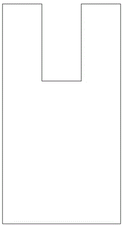
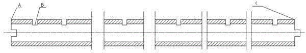
[0021] like Figure 4 Shown is the structural schematic diagram of the steel pipe comb bar, wherein Figure 4 #1 is the hook joint, #2 is the steel wire, #3 is the steel pipe, and #4 is the joint of the steel wire rope. The steel pipe #3 is set on the steel wire #4 to form a composite bar, and the length and needle distance of the bar are determined according to the groove distance on the steel pipe and the number of steel pipes. The steel pipe and steel wire are connected by glue. The steel pipe has an outer diameter of 2.0 mm and an inner diameter of 1.36 mm. The diameter of the steel wire matches the inner diameter of the steel pipe.

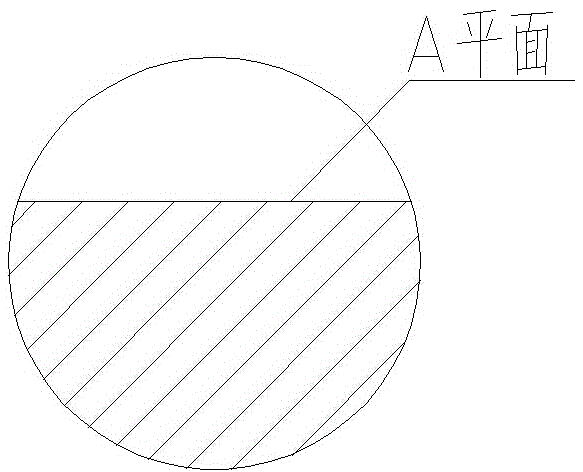
[0022] Figure 5 Yes Figure 4 The enlarged schematic diagram of I in the Figure 4 It can be seen that the needle distance is 2.117, that is, 24 needle distances 2, the needle distance from B to C is an even multiple of 2 needle distances, all even needle distances can be arranged, and different numbers of steel pipes are used to deter...

Embodiment 2

[0024] The stitch distance from A to B is 1.058, that is, one stitch length, and one stitch length is added to the even number stitch length to form an odd number stitch length. Any stitch length can then be obtained with any mating needle.


PUM

PropertyMeasurementUnit
lengthaaaaaaaaaa

Abstract

A steel pipe combined guide bar is disclosed, wherein the steel pipe combined guide bar comprises steel wire parts and steel pipe parts. The guide bar is constituted by sleeving a plurality of steel pipe parts on the steel wire parts. The steel pipe is provided with 1-2 clamping slots. The steel pipe combined guide bar has the advantages that only a standard jacquard needle and a 364.3 measure are required for determining the zero point of the guide bar, due to the fact that the slots are separated from the steel wires; and a glue is used (before gluing, the pipe can rotate and move on the steel wire for aligning the position). The glue is conveniently dried after 3 minutes; and then a guide bar is formed by sleeving 13 pipes head-to-tail. The length of the guide bar can be determined as need. Odd number needle pitch and even number needle pitch can be arranged, accordingly meeting the requirements of different needle pitches.

Description

technical field [0001] The invention relates to the technical field of knitting equipment, in particular to a bar device of a high-speed lace warp knitting machine. Background technique [0002] In the knitting machine, the warp knitting machine is used to weave fabrics with complex patterns, and the warp knitting machine drives the pattern needles to move through the bar, so as to weave the weaving thread into the fabric. At present, the comb bars used in high-speed lace warp knitting machines on the market are generally made of steel wires. They can be divided into two types based on their appearance. One is that there are grooves on the steel wire comb bars, such as figure 1 As shown, the groove is directly milled out on the steel wire with a milling cutter, and the needle matching the bar is embedded in the groove, as shown in Figure 4 shown. The other is that there is no groove on the steel wire comb, and the flower needle and the steel wire comb are connected by glu...

Claims


Application Information

Patent Timeline
Patent Type & Authority Applications(China)
IPC IPC(8): D04B27/24
Inventor 谢俊
Owner 李藕英
Why Eureka
Try Eureka