Dry indirect-cooling-storage type peak cooling system of thermal power generating unit

A thermal power unit, peak cooling technology, applied in steam/steam condensers, lighting and heating equipment, etc., can solve the problems of stable operation of the unit and negative impact on economy, high cost of direct air cooling tower area, and inability to solve vacuum fluctuations, etc. Achieve the effects of reducing rotor fatigue loss, improving safety and reliability, and reasonable design

Active Publication Date: 2015-07-29
BEIJING NORTH SANHE ENERGY TECH
View PDF8 Cites 2 Cited by
  • Summary
  • Abstract
  • Description
  • Claims
  • Application Information

AI Technical Summary

Problems solved by technology

In actual operation, direct air-cooled thermal power units will have high back pressure and frequent fluctuations in summer, and the vacuum can reach 40kPa, which will have a great negative impact on the stable operation and economy of the unit
The current solution is mainly to increase the area of ​​the original direct air cooling tower and the wet peak cooler. The cost of adding a direct air cooling tower is high and cannot solve the problem of vacuum fluctuations. Although the cost of the wet peak cooler is slightly lower, it is in operation. It needs to consume a lot of water resources to achieve the purpose of reducing back pressure, and the external spray cooler consumes a lot of demineralized water, which is contrary to the original intention of water saving in establishing a direct air cooling unit

Method used


Image

  • Dry indirect-cooling-storage type peak cooling system of thermal power generating unit

Examples


Embodiment Construction

[0020] The following will clearly and completely describe the technical solutions in the embodiments of the present invention with reference to the accompanying drawings in the embodiments of the present invention. Obviously, the described embodiments are only some, not all, embodiments of the present invention. All other embodiments obtained by persons of ordinary skill in the art based on the embodiments of the present invention belong to the protection scope of the present invention.

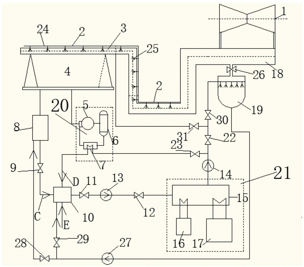
[0021] Such as figure 1 As shown, a thermal power unit dry-type indirect cold storage peak cooling system according to an embodiment of the present invention includes a steam turbine low-pressure cylinder 1, and the lower end of the steam turbine low-pressure cylinder 1 is connected with an exhaust pipe 18 matching it. The steam pipe 18 is connected to the jet condenser 19 through the butterfly control valve 26, and the jet condenser 19 is connected to the condensate tank 8 through the conden...


PUM


Abstract

The invention discloses a dry indirect-cooling-storage type peak cooling system of a thermal power generating unit. The dry indirect-cooling-storage type peak cooling system comprises a turbine low pressure cylinder, wherein the lower end of the turbine low pressure cylinder is connected with an exhaust steam pipe matched with the turbine low pressure cylinder, the exhaust steam pipe is connected with a jet-type condenser through a butterfly control valve and is connected with a condensing water tank through a condensing water pump, and another end of the exhaust steam pipe is connected with an air cooled condenser; the exhaust steam pipe is provided with a stem dispensing pipeline of the air cooled condenser on which a cooling and mixing device is arranged; the cooling and mixing device comprises a cooling water delivery pipeline and a plurality of cooling water nozzles formed in the cooling water delivery pipeline, the air cooled condenser is connected with a circulating water collecting tank through a condensed water tank, and the circulating water collecting tank is connected in a cooling chamber in the cooling system through a water taking pump; the cooling chamber is respectively connected with a dry air forced ventilation cooling system and a voltage compression refrigerating system, the cooling chamber is connected with the jet-type condenser through the circulating water collecting tank, and the air cooled condenser is connected to a water circulating vacuum pump in an air extractor and is sequentially connected with a gas water separator and a cooler; one end of the cooler is connected with a cooling chamber, and the other end of the cooler is connected with a circulating water collection tank.

Description

technical field [0001] The invention relates to the technical field of thermodynamic cycles, in particular to a dry-type indirect cold storage type peak cooling system for a thermal power unit. Background technique [0002] With the steady and rapid development of my country's economy, the demand for energy consumption in the whole society is gradually expanding, and the demand for electric energy in the manufacturing industry dominated by light and heavy industries is increasing day by day. The pressure of economic transformation has also made the original south of the developed areas of the manufacturing industry gradually complete the transfer to the north's new and old industrial areas, and the extension of the manufacturing industry chain. In order to ensure the successful transfer of industrial enterprises from south to north and provide sufficient energy support, the northern region has vigorously developed the power industry since 2000, especially in Shanxi, Inner Mo...

Claims


Application Information

Patent Timeline
Patent Type & Authority Applications(China)
IPC IPC(8): F28B11/00
Inventor 梁双印高满达王国生
Owner BEIJING NORTH SANHE ENERGY TECH
Why Eureka
Try Eureka