Supercharge Your Innovation With Domain-Expert AI Agents!

Reactive power compensation method for transformer

A compensation method and transformer technology, applied in the directions of reactive power compensation, reactive power adjustment/elimination/compensation, AC network circuits, etc., can solve the problem of inability to compensate for the power factor of the transformer, achieve accurate compensation, fast dynamic response, and solve no problem. The effect of the work problem

Inactive Publication Date: 2015-07-29
CHENGDU MOLO ELECTRIC
View PDF5 Cites 4 Cited by
  • Summary
  • Abstract
  • Description
  • Claims
  • Application Information

AI Technical Summary

Problems solved by technology

[0015] In order to overcome the problem in the prior art that the SVC capacitor switching equipment cannot compensate the power factor of the transformer at all when the frequency of load changes is high, the present invention aims to provide a compensation method for reactive power compensation of the transformer, which is based on Transformer model, when the active power filter APF is used to compensate the reactive power and harmonics of the transformer back-end load, the reactive power of the transformer is accurately predicted, and the reactive power generated by the transformer is also compensated

Method used


Image

  • Reactive power compensation method for transformer
  • Reactive power compensation method for transformer
  • Reactive power compensation method for transformer

Examples


Embodiment Construction

[0039] The present invention will be further described in detail below in conjunction with test examples and specific embodiments. However, it should not be understood that the scope of the above subject matter of the present invention is limited to the following embodiments, and all technologies realized based on the content of the present invention belong to the scope of the present invention.

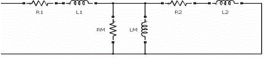
[0040] A compensation method for reactive power compensation of a transformer, characterized in that it includes reactive power compensation generated by the excitation inductance at no-load and reactive power compensation generated by the current after the load on the leakage inductance, as follows:

[0041] Step 1: Calculate the reactive power Q generated at no-load according to the transformer reactive power calculation method when the transformer model is no-load 空载 ;

[0042] Step 2: ②Calculate the reactive power Q generated under load according to the transformer reactive powe...


PUM


Abstract

The invention discloses a reactive power compensation method for a transformer and relates to the technical field of electric energy treatment. The reactive power compensation method comprises the following steps: 1, calculating reactive power Q idle load generated in the idle load according to a reactive power calculation method for the transformer in the idle load of a transformer model; 2, calculating reactive power Q load generated in the load according to the reactive power calculation method for the transformer in the load; 3, calculating the total reactive power quantity of the transformer; 4, compensating the transformer by using the total reactive power quantity obtained in the step 3 as a reactive power compensation instruction for the transformer. According to the reactive power compensation method for the transformer, high-voltage-side voltage current does not need to be sampled, the reactive power of the transformer is predicted through a user load and is compensated by adjusting the output of an SVG (Static Var Generator), the reactive power of an access network is reduced, the dynamic response is quick, the compensation is accurate, the problem of resonance does not exist, and the problem of reactive power of the transformer can be effectively solved.

Description

technical field [0001] The invention relates to the technical field of electric energy management, in particular to a compensation method for reactive power compensation of a transformer. Background technique [0002] With the rapid development of modern industry, industrial power consumption is increasing, and industrial electrical equipment is dominated by motors and high-power rectifiers. Therefore, reactive power and harmonics have become the most prominent problems in the quality of industrial power consumption. Large power transmission line loss will increase and reduce the utilization rate of electric energy. The power factor is an important indicator to measure the utilization rate of electric energy. Its definition is as follows: [0003] ρ = Q P 2 + Q 2 - - - ...

Claims


Application Information

Patent Timeline
IPC IPC(8): H02J3/18
CPCY02E40/30H02J3/1892
Inventor 邹军
Owner CHENGDU MOLO ELECTRIC
Features
  • R&D
  • Intellectual Property
  • Life Sciences
  • Materials
  • Tech Scout
  • Unparalleled Data Quality
  • Higher Quality Content
  • 60% Fewer Hallucinations
Learn More