
Adjusting energy of a particle beam

A particle and energy technology, applied in the field of energy regulation of particle beams, can solve problems such as reducing the therapeutic effect and endangering particle beams

Active Publication Date: 2015-07-29
MEVION MEDICAL EQUIP CO LTD
View PDF16 Cites 17 Cited by
  • Summary
  • Abstract
  • Description
  • Claims
  • Application Information

AI Technical Summary

Problems solved by technology

The result is that the particle beam is prevented from escaping from the exit channel, or the portion of the particle beam that does escape is compromised, thereby reducing the therapeutic effect

Method used


Image

  • Adjusting energy of a particle beam
  • Adjusting energy of a particle beam
  • Adjusting energy of a particle beam

Examples


Embodiment approach

[0111] Figure 15A top view of a portion of cavity 700 in which particles are accelerated in orbit (eg, on an outward spiral orbit) is shown. A particle source 701, an example of which is described above, is positioned about the center of the cavity. Charged particles (eg, protons or ions) are extracted from a plasma column generated by particle source 701 . The charged particles are accelerated outward in orbit towards and eventually to the magnetic regenerator 702 . In this example embodiment, the regenerator 702 is a ferromagnetic structure made, for example, of steel, iron, or any other type of ferromagnetic material. Regenerator 702 alters the background magnetic field causing outward orbital acceleration. In this example, regenerator 702 increases the magnetic field (eg, it provides a bump in the magnetic field). The bump in the background magnetic field affects the particle trajectory in a way that causes the trajectory to move outward towards the extraction channel...


PUM


Abstract

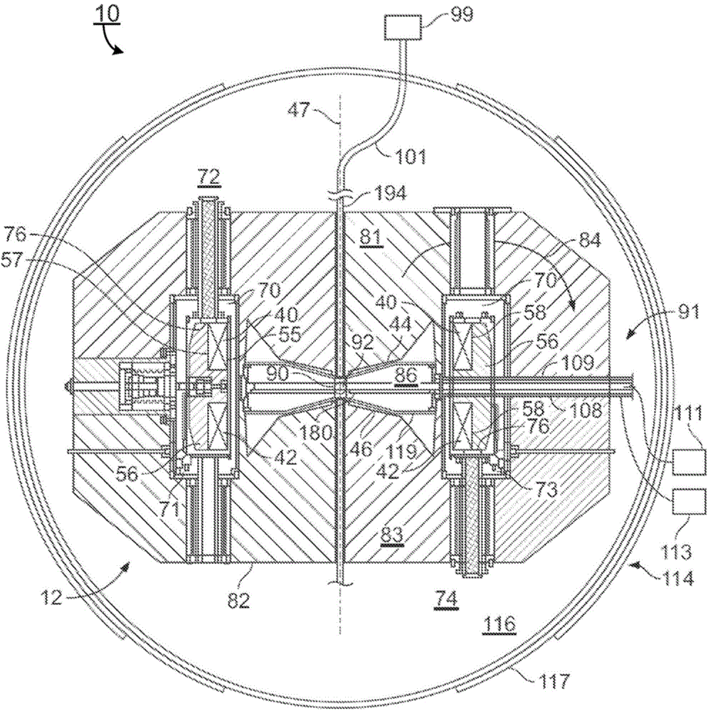
An example particle accelerator includes a coil to provide a magnetic field to a cavity; a particle source to provide a plasma column to the cavity; a voltage source to provide a radio frequency (RF) voltage to the cavity to accelerate particles from the plasma column, where the magnetic field causes particles accelerated from the plasma column to move orbitally within the cavity; an enclosure containing an extraction channel to receive the particles accelerated from the plasma column and to output the received particles from the cavity; and a structure arranged proximate to the extraction channel to change an energy level of the received particles.

Description

[0001] Cross reference related applications [0002] Priority is hereby claimed to US Provisional Application No. 61 / 707,515, filed September 28, 2012. The contents of this US Provisional Application No. 61 / 707,515 are hereby incorporated by reference into this disclosure. technical field [0003] This disclosure generally relates to energy modulation of particle beams, such as proton or ion beams, for use in particle therapy systems. Background technique [0004] Particle therapy systems use accelerators to generate beams of particles that are used to treat diseases, such as tumors. In operation, a particle beam is accelerated within the cavity of the particle accelerator and removed from the cavity through an extraction channel. In order to track the extraction channel, the particle beam must be properly energized. Insufficient energy, the particle beam collides with the inner edge of the exit channel. Too much energy and the particle beam collides with the outer edge ...

Claims


Application Information

Patent Timeline
Patent Type & Authority Applications(China)
IPC IPC(8): A61N5/10H05H7/12
CPCH05H13/02H05H7/04H05H7/10H05H2007/004A61N2005/1095A61N5/1077
Inventor G.T.兹瓦特K.P.高尔J.范德兰S.罗森塔尔M.巴斯基C.D.奥尼尔三世K.Y.弗兰岑
Owner MEVION MEDICAL EQUIP CO LTD
Learn More