Jig for pipeline laser cutting machine and pipeline laser cutting machine

A laser cutting machine and tooling fixture technology, which is applied in the direction of manufacturing tools, laser welding equipment, welding/cutting auxiliary equipment, etc., can solve the problem of waste of remaining material in the remaining length, and achieve simple structure, small size and volume, and reliable clamping hold a fixed effect

Active Publication Date: 2015-08-05
湖北金飞翼智能科技有限公司
View PDF7 Cites 19 Cited by
  • Summary
  • Abstract
  • Description
  • Claims
  • Application Information

AI Technical Summary

Problems solved by technology

[0005] In view of the above defects or improvement needs of the prior art, the present invention provides a tooling fixture for a pipeline laser cutting machine and a pipeline laser cutting machine including the tooling fixture, which solves the problem by optimizing the structure of the tooling fixture The current cutting machine has the waste of excess material caused by the excessive remaining length of the pipe after the last cutting, and at the same time, the pipe is firmly and reliably clamped, and can adapt to the needs of various working conditions such as manual pipe replacement.

Method used


Image

  • Jig for pipeline laser cutting machine and pipeline laser cutting machine
  • Jig for pipeline laser cutting machine and pipeline laser cutting machine
  • Jig for pipeline laser cutting machine and pipeline laser cutting machine

Examples


Embodiment Construction

[0028] In order to make the object, technical solution and advantages of the present invention clearer, the present invention will be further described in detail below in conjunction with the accompanying drawings and embodiments. It should be understood that the specific embodiments described here are only used to explain the present invention, not to limit the present invention. In addition, the technical features involved in the various embodiments of the present invention described below can be combined with each other as long as they do not constitute a conflict with each other.

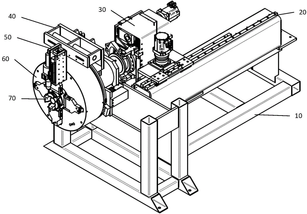
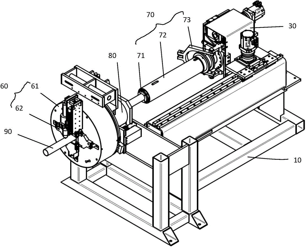
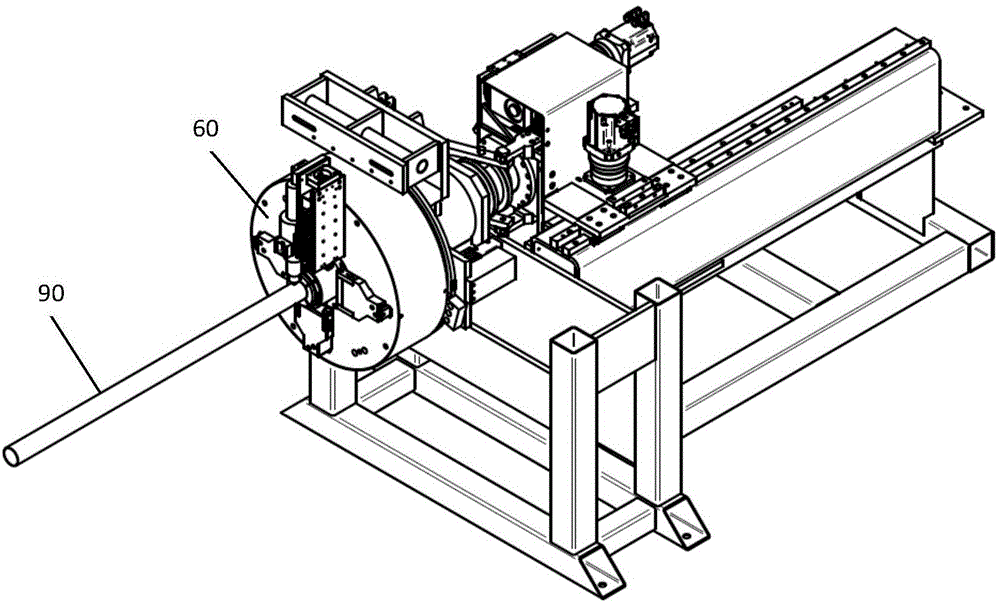
[0029] The tooling and fixture for pipeline laser cutting machine constructed according to the embodiment of the present invention is as follows: Figure 1-3 As shown, it includes a cutting and clamping unit 60 , a guide mechanism 80 and a feeding and clamping mechanism 70 .

[0030] The feeding clamping mechanism 70 is arranged on the machine tool base 10, and can reciprocate along the Y-axis ...


PUM


Abstract

The invention discloses a jig for a pipeline laser cutting machine. The jig for the pipeline laser cutting machine comprises a cutting clamping unit, a guide mechanism and a feed clamping mechanism, wherein the cutting clamping unit is provided with a disc, the end surface of one side of the disc is provided with multiple clamping claws for clamping the pipeline tightly, the guide mechanism is an annular body which is axially arranged with the disc and used for guiding the pipeline entering into the disc, and the feed clamping mechanism is arranged behind the guide mechanism and used for tightly clamping the tail end of the long pipeline to be cut and conducting cutting and feeding. The feed clamping mechanism is a hollow cylinder body, the diameter of the periphery of the cylinder body is smaller than the inner diameter of the center through hole of the disc, thus the feed clamping mechanism can directly enter the center through hole of the disc, enables the clamping claws of the cutting clamping unit to clamp the tail end pipe wall of the pipeline and completes the final cutting of the pipeline. The jig for the pipeline laser cutting machine can realize accurate and efficient cutting of the pipeline, especially can greatly reduce the material waste caused by two much remaining lengths of the pipeline in the conventional cutting machinery.

Description

technical field [0001] The invention belongs to the technical field of pipeline laser cutting, and in particular relates to a fixture for a pipeline laser cutting machine and a pipeline laser cutting machine with the fixture. Background technique [0002] The pipe usually needs to be cut to the length of the corresponding specification before it can be used. For the cutting of metal pipes, laser cutting is widely used in the industry. This technology uses the energy released when the laser beam irradiates the surface of the pipe wall to melt and vaporize the metal. Through the lens and mirror, the laser beam is concentrated in a small area. The high concentration of energy enables rapid localized heating to vaporize metallic materials. In addition, because the energy is so concentrated, only a small amount of heat is transferred to other parts of the steel, causing little or no deformation. Blanks of complex shapes can be cut very accurately with a laser, and the cut blan...

Claims


Application Information

Patent Timeline
Patent Type & Authority Applications(China)
IPC IPC(8): B23K26/38B23K37/053
CPCB23K26/38B23K37/053
Inventor 熊震何傲杰陈静孙博林刘佳杨菁
Owner 湖北金飞翼智能科技有限公司
Why Eureka
Try Eureka